Domoticz Part 2: WiFi remote thermometer - weather station, dual digit precision – it’s time to look at ESP8266 for beginners
Last time we installed Domoticz, and soon we will move to Z-Wave, but first – let’s take a look at fantastic little gadget: ESP8266
What is an ESP8266?
ESP8266 (also called ESP here) is a SoC – System on a Chip, which in our case is – CPU/RAM/FLASH with GPIO and WiFi interface – so another mini komputer with wireless interface. You can think of it as scaled down version of Raspberry Pi, less power hungry, but with own WLAN and a lot (minimum 2) GPIOs. Ad it runs it’s own WWW server!
- CPU – 80MHz (much faster than Arduino, much slower than Pi)
- RAM – 64kB for instructions and 96kB
- ROM – 64kB (just for boot)
- FLASH: 4Mb (512kB)
- WLAN: radio 2,4GHz – 802.11 b/g/n with WPA2
- GPIO, I2C, ADC, SPI, PWM
- Power: 3,3V (just what we have available using PIN 1 in Raspbery Pi)
- Interpreter and LUA compiler (sic!). Or pure C using Arduino IDE
- Price: $3. Yes. 3 US dollars
The SoC’s manufacturer is Espressif, other companies produce ready boards with interfaces and antennas:
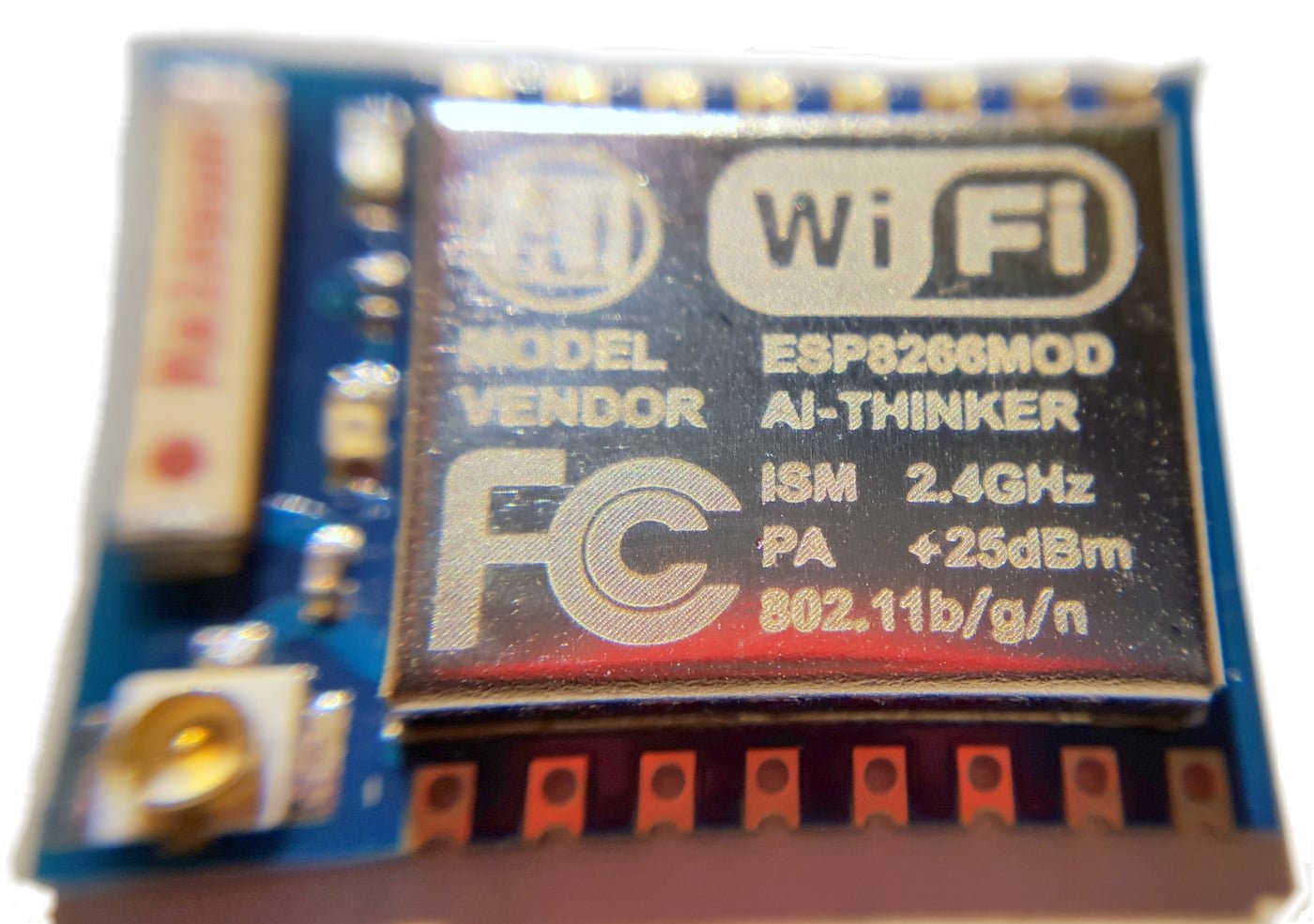
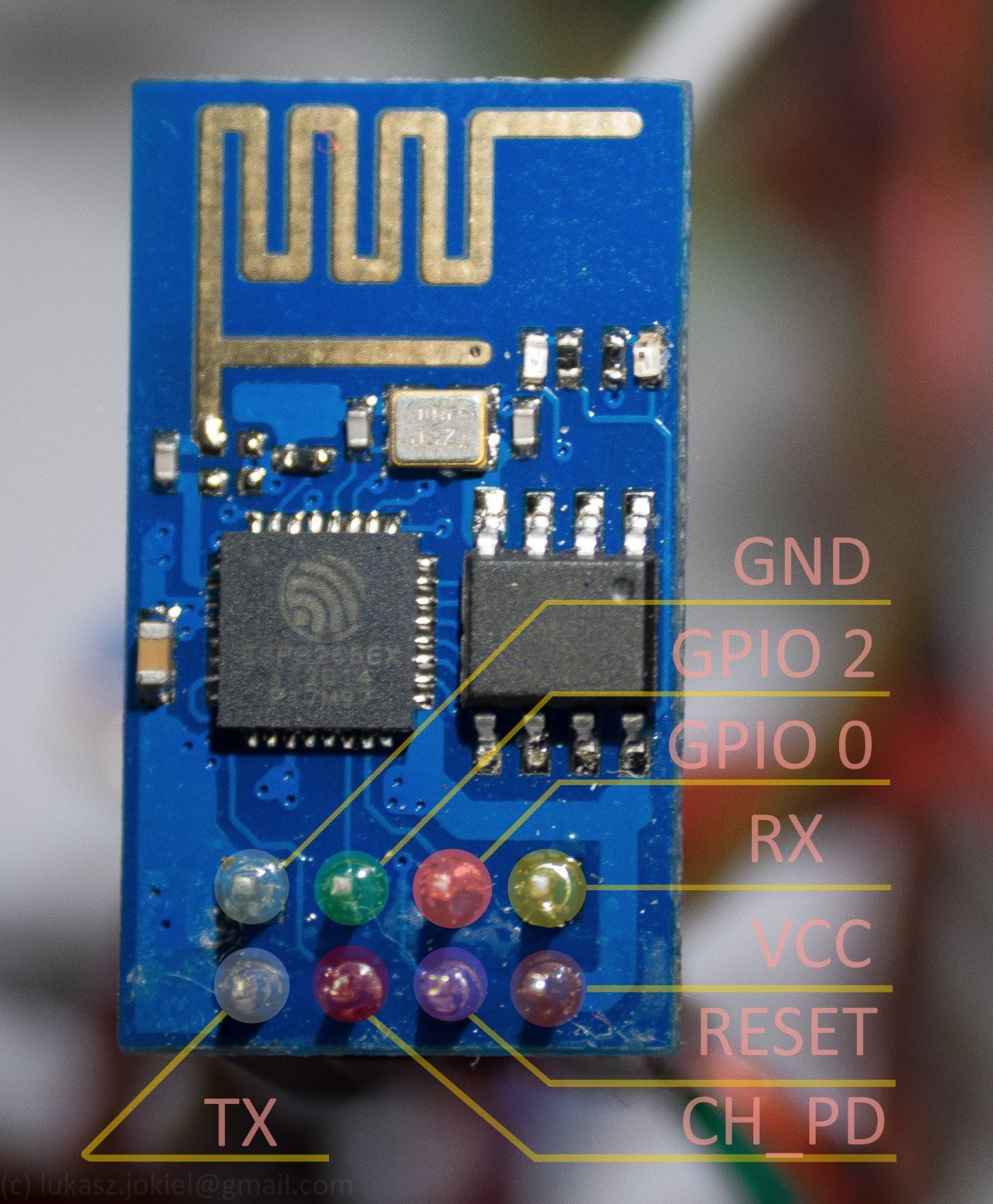
- ESP-01 (v1 and v2) – you get pins for +3,3V, GND, TX,RX and GPIO 0 i GPIO 2 (they spawn pull-up). WiFi antenna is printed on the module. Very popular due to price, best for beginners – it’s easy to connect it to Pi
- ESP-03 – we get 8x GPIO
- ESP-12 – SoC with shielding, better antenna and 10x GPIO
But why?
Let’s summarize: we have a possibility to use two or more GPIOs on WiFi enabled device, using very little power (10x less than RPi) – ideal for a weather station sensor. We can write a small program that would update the values in Domoticz (i.e. sensors) – because we can not only use the internal Web server but also sent periodically data to Domoticz – using nodejs or JSON format URL that Domoticz understands well. The latter is much more stable – and it’s great for starters.
It’s decided then! We’re building remote thermometer – based on ready examples.
Hardware
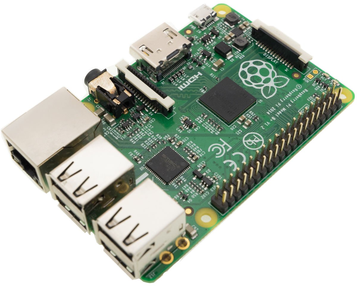
- Raspberry Pi (any model – A, B, B+, 2 or 3 or even Pi Zero)
- ESP8266 (any version, the best for start is ESP-01 with two GPIOs)
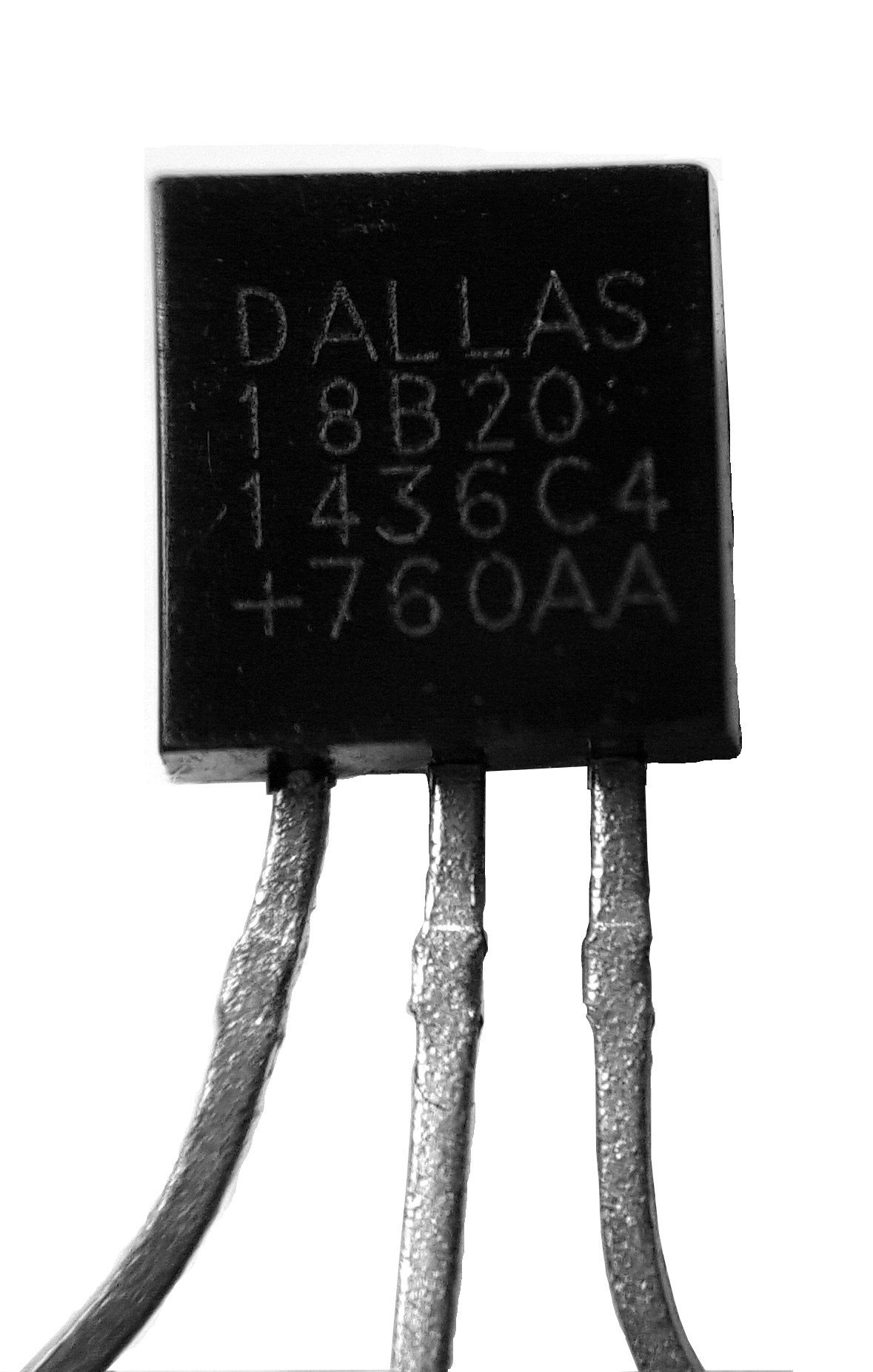
- Dallas DS18b20 Thermometr – we can get chip or waterproof versions
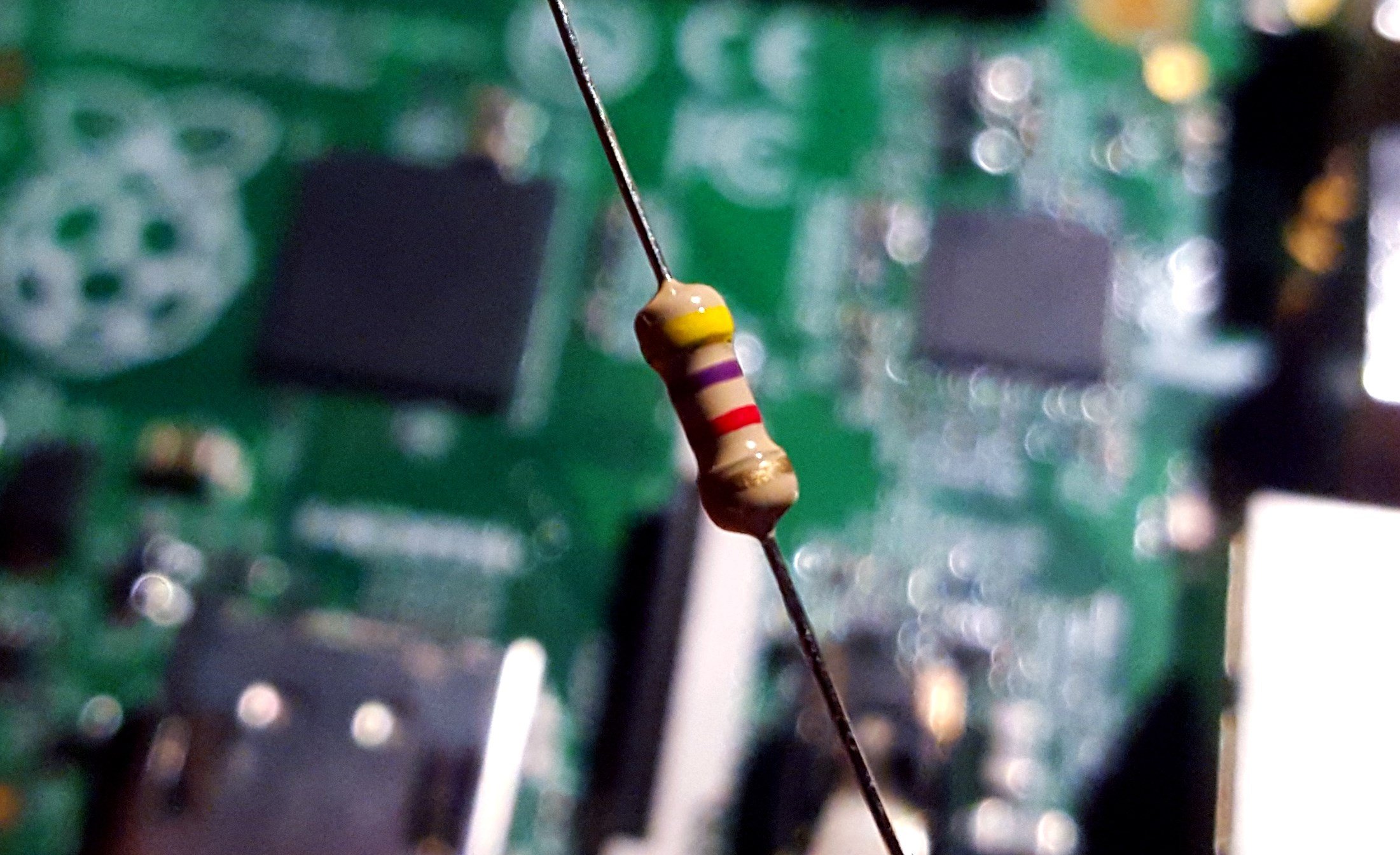
- 4,7k resistor – allows good readout from thermometer (pulls-up the DATA PIN), but if you are not getting results – change it to 2,2k:
- OPTIONAL: Step-down module which will provide stable 3,3V out of input 5V (just make a search on your favorite portal for: step-down 3.3V)
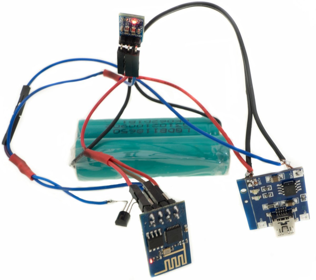
- OPTIONAL: One or two Li-Ion type 18650 batteries – you can extract them from old notebook battery packs or power banks – but be carefull when disasembling the pack – 18650 are very dangerous when short or punctured! It could also cell phone battery – any Li-Ion that you can easily set-up. Fully charged battery is about max 4,2V and total capacity of around 2300mAh-2500mAh
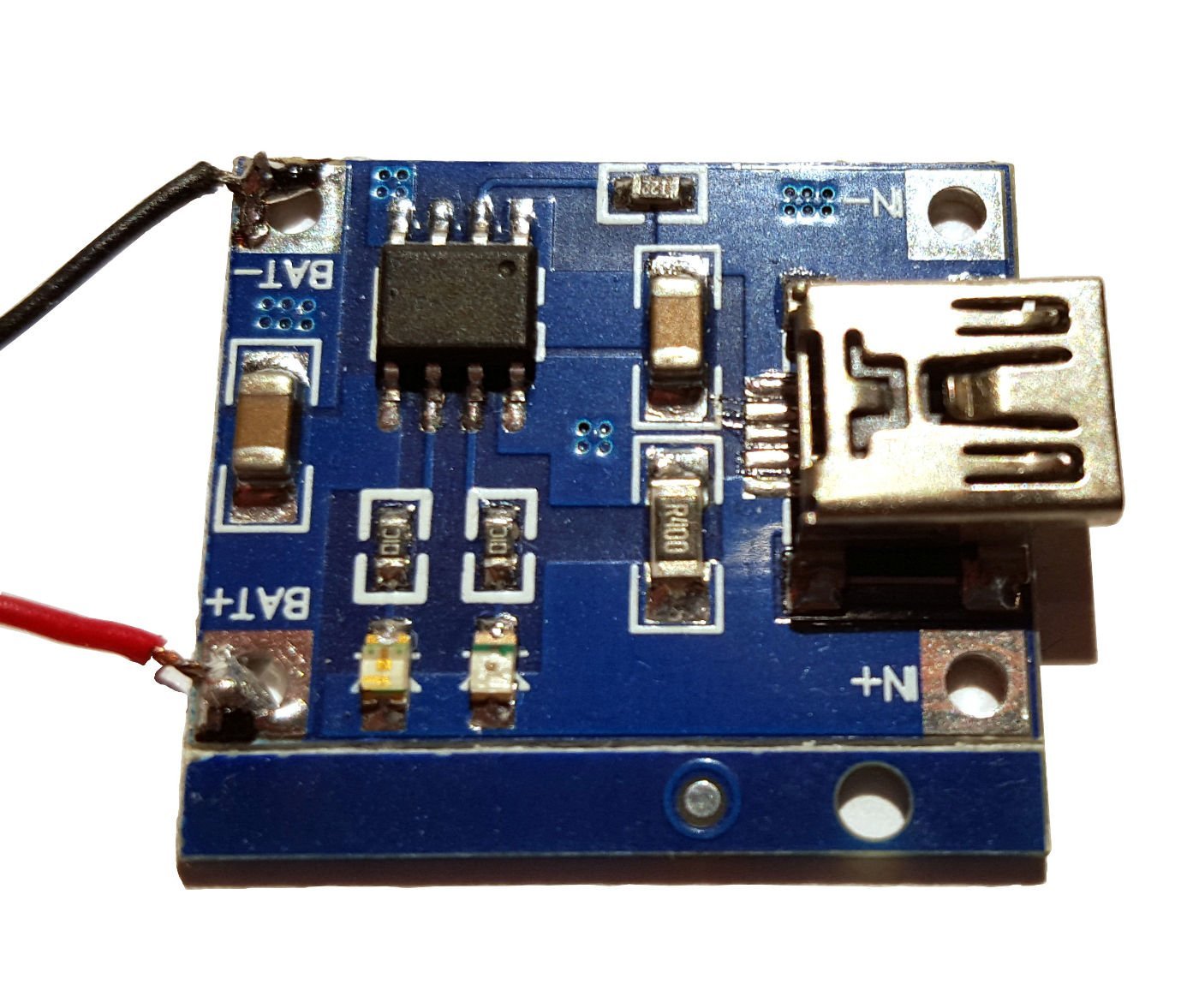
- OPTIONAL: charging module for working at 5V to properly charge and protect Li-Ion battery – it has USB and micro-USB connectors for input and output and soldiering pads for 18650. Check on how you can attach 18650 (be extra careful when soldering!)
Connecting the ESP8266 module and updating the firmware
The ESP8266 has a standard UART – with TX,RX PINs, 3V logic – and it’s great since we can use the Raspberry Pi as a console!. In my optionion this is the best way to deal with this module. Our Raspberry Pi UART port is by default used as RPi own system console, so we have to free it to use as communications channel to ESP8266. To do that we have to delete in /boot/cmdline.txt this part: console=/dev/ttyAMA0,115000. Now let’s reboot RPi.
We should install now:
- picocom for Raspberry Pi OS (formerly Raspbian) (serial console)
- firmware for ESP8266 supporting LUA interpreter from NodeMCU z https://github.com/nodemcu/nodemcu-firmware/releases
- esptool.py – python program used to upgrade the unit from https://github.com/themadinventor/esptool
- luatool.py – python program used to upload ready LUA scripts to ESP8266 from https://github.com/4refr0nt/luatool
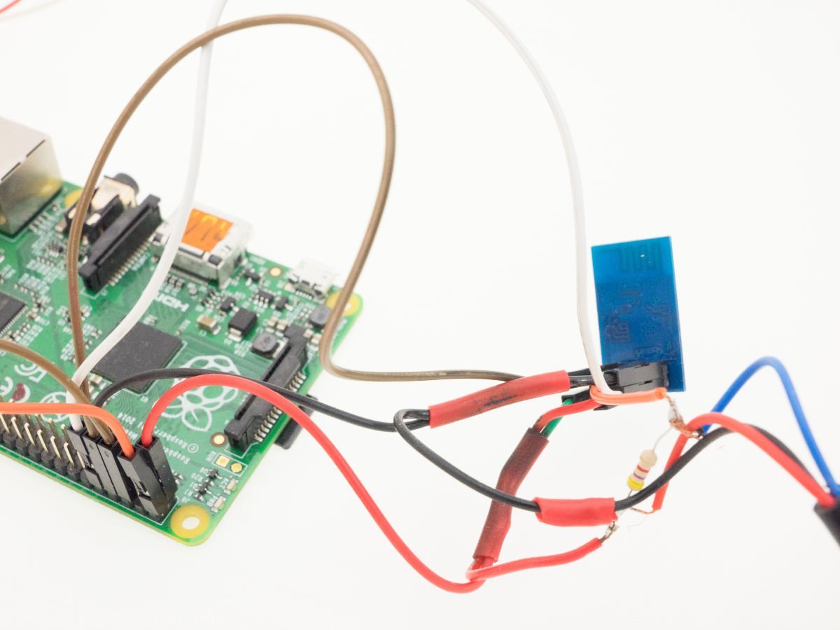
Since ESP8266 is often used as Arduino module it comes to us with a firmware that uses AT commands – just like modems do. We will use the NodeMCU firmware – that uses LUA intereter/compiler – another very nice BASIC-like type of software (very powerfull!). At the time of writting we had: nodemcu_integer_0.9.6-dev_20150704.bin version available with the tool – esptool.py. Let’s hook up the ESP8266 to Raspberry Pi:
We will be using 3,3V as VCC form RPi: +3,3V connecting to VCC and CH_PD on ESP (look at the picture). Now it’s not recommended for a longer period, because ESP8266 can draw 3x more than 3,3V PIN on RPi can support!
GND from RPi to GND at ESP
PIN 13 on RPi to TX on ESP, and PIN 14 on RPi to RX on ESP
Additionaly, we have to connect GPIO 0 to GND on ESP-01, to allow firmware upgrade (and re-power ESP after connecting). Upgrading is as easy as this:
Installing proper serial support library for python:
sudo apt-get install python-serialUpdating the firmware:
python esptool.py -p /dev/ttyAMA0 write_flash 0x000000 nodemcu_integer_0.9.6-dev_20150704.binIf GPIO0 is NOT connected to GND you will see this error:
pi@raspberrypi ~/esp8266 $ python esptool.py -p /dev/ttyAMA0 write_flash 0x000000 nodemcu_integer_0.9.6-dev_20150704.bin
Connecting...
Traceback (most recent call last):
  File "esptool.py", line 353, in
    esp.connect()
  File "esptool.py", line 138, in connect
    raise Exception('Failed to connect')
Exception: Failed to connect
If GPIO0 is connected to GND and re-powering of the ESP unit – firmware will be upgraded:
python esptool.py -p /dev/ttyAMA0 write_flash 0x000000 nodemcu_integer_0.9.6-dev_20150704.bin
Connecting...
Erasing flash...
Writing at 0x00005800... (5 %)
Writing at 0x00031800... (45 %)
Writing at 0x00057c00... (80 %)
Writing at 0x0006dc00... (100 %)

Leaving...
After successful upgrade we should get to know our new toy. To do that we need serial console -let’s install picocom and enter:
picocom -b 9600 --omap crcrlf /dev/ttyAMA0We can see the “>” prompt, so if you already know LUA you can start testing or use: official examples form NodeMCU..
First, let’s get IP address via WiFi, enter the commands line per line:
print(wifi.sta.getip())
--nil
wifi.setmode(wifi.STATION)
wifi.sta.config("SSID","password")
print(wifi.sta.getip())
--192.168.1.12
You need to change the SSID and password to correct values for your home network – and ESP will connec to Access Point and will ask for IP address via DHCP client. Great, we have IP address now. Now, let’s connect the Dallas DS18b20. It’s a very cheap sensor, that is supported by NodeMCU example – download from the module library the file : ds18b20.lua.
But we need changes, since we will get only single digit precision in Celsius mode – find the line:
t = t / 10000and replace with:
t = t / 100Double digit precision is ready! Changed file looks like this:
--------------------------------------------------------------------------------
-- DS18B20 one wire module for NODEMCU
-- NODEMCU TEAM
-- LICENCE: http://opensource.org/licenses/MIT
-- Vowstar <[email protected]>
-- 2015/02/14 sza2 <[email protected]> Fix for negative values
--------------------------------------------------------------------------------

-- Set module name as parameter of require
local modname = ...
local M = {}
_G[modname] = M
--------------------------------------------------------------------------------
-- Local used variables
--------------------------------------------------------------------------------
-- DS18B20 dq pin
local pin = nil
-- DS18B20 default pin
local defaultPin = 9
--------------------------------------------------------------------------------
-- Local used modules
--------------------------------------------------------------------------------
-- Table module
local table = table
-- String module
local string = string
-- One wire module
local ow = ow
-- Timer module
local tmr = tmr
-- Limited to local environment
setfenv(1,M)
--------------------------------------------------------------------------------
-- Implementation
--------------------------------------------------------------------------------
C = 0
F = 1
K = 2
function setup(dq)
  pin = dq
  if(pin == nil) then
    pin = defaultPin
  end
  ow.setup(pin)
end

function addrs()
  setup(pin)
  tbl = {}
  ow.reset_search(pin)
  repeat
    addr = ow.search(pin)
    if(addr ~= nil) then
      table.insert(tbl, addr)
    end
    tmr.wdclr()
  until (addr == nil)
  ow.reset_search(pin)
  return tbl
end

function readNumber(addr, unit)
  result = nil
  setup(pin)
  flag = false
  if(addr == nil) then
    ow.reset_search(pin)
    count = 0
    repeat
      count = count + 1
      addr = ow.search(pin)
      tmr.wdclr()
    until((addr ~= nil) or (count > 100))
    ow.reset_search(pin)
  end
  if(addr == nil) then
    return result
  end
  crc = ow.crc8(string.sub(addr,1,7))
  if (crc == addr:byte(8)) then
    if ((addr:byte(1) == 0x10) or (addr:byte(1) == 0x28)) then
      -- print("Device is a DS18S20 family device.")
      ow.reset(pin)
      ow.select(pin, addr)
      ow.write(pin, 0x44, 1)
      -- tmr.delay(1000000)
      present = ow.reset(pin)
      ow.select(pin, addr)
      ow.write(pin,0xBE,1)
      -- print("P="..present)
      data = nil
      data = string.char(ow.read(pin))
      for i = 1, 8 do
        data = data .. string.char(ow.read(pin))
      end
      -- print(data:byte(1,9))
      crc = ow.crc8(string.sub(data,1,8))
      -- print("CRC="..crc)
      if (crc == data:byte(9)) then
        t = (data:byte(1) + data:byte(2) * 256)
        if (t > 32767) then
          t = t - 65536
        end
        if(unit == nil or unit == C) then
          t = t * 625
        elseif(unit == F) then
          t = t * 1125 + 320000
        elseif(unit == K) then
          t = t * 625 + 2731500
        else
          return nil
        end
        t = t / 100
        -- print("Temperature="..t1.."."..t2.." Centigrade")
        -- result = t1.."."..t2
        return t
      end
      tmr.wdclr()
    else
    -- print("Device family is not recognized.")
    end
  else
  -- print("CRC is not valid!")
  end
  return result
end

function read(addr, unit)
  t = readNumber(addr, unit)
  if (t == nil) then
    return nil
  else
    return t
  end
end

-- Return module table
return
Save it for later – we will upload this to ESP in a moment- first let’s see how to autostart programs on ESP
Autostarting programs on ESP8266
ESP8266 with NodeMCU firmware after booting executes the init.lua, which is residing on the flash. It is extremely important that init.lua is TESTED and won’t put the ESP in boot-loop. We all heard horror stories about bad loop that executes indefinitely. Rule of a thumb – our init.lua should be short, minimal. In our case – let’s just get IP address and run the domoticz.lua which will report the temperature back to domoticz. Also – let’s try to have a backup WiFi in case we cannot connect with main – we can use the second WiFi network for debug purposes. Another important part of init.lua is the pause. Before getting/asking for IP address we should have enough time to issue a command to delete the init.lua file, so we can replace it in case no WiFi network is available. Our init.lua should look like this example:
--init.lua
 wifi.setmode (wifi.STATION)
 wifi.sta.config("MOJE SSID 1","tajne_haslo_do_ssid_1")
 wifi.sta.connect()
 tmr.alarm(1, 6000, 1, function()
  if wifi.sta.getip()== nil then
  print("Brak polaczenia i IP, probuje dalej...")
  wifi.sta.config("DRUGIE ZAPASOWE SSID","jeszcze_bardziej_tajne")
  wifi.sta.connect()
 else
  tmr.stop(1)
 print("Tryb pracy ESP8266: " .. wifi.getmode())
 print("Adres MAC ESP8266: " .. wifi.ap.getmac())
 print("Sukces, adres IP: "..wifi.sta.getip())
 dofile ("domoticz.lua")
 end
 end)
This init.lua changes ESP mode into AP client (ESP is also used as AP), sets the SSID, password and issues command to connect to home AP. Next – after 6000ms we check if wifi.sta.getip() returns something else than “nil” (nothing). If not – we move to configure backup network and we repeat that every 6000ms until ESP gets IP address. This 6000ms is here to login via serial console and delete the init.lua if we do not have any WiFi network. But if all goes well – ESP runs via dofile, another script that does the readout of temperature and sends it to domoticz – it’s called: domoticz.lua
Main temperature readout program, sending data to Domoticz:
--domoticz.lua
require('ds18b20')
gpio0 =3
gpio2 =4
ds18b20.setup(gpio2)
t=ds18b20.read()
print("Raw data readout from ds28b20:" .. t .. " C\n")
if(t==nil) then
t=0
end
tmr.alarm(0,240000, 1, function()
 t=ds18b20.read()
 tpre=t/100
 tsub=string.sub(t,-2)
 temp=tpre .. "." .. tsub
 print("Temperature being sent:" .. temp .. " C\n")
 conn=net.createConnection(net.TCP, 0)
 conn:on("receive", function(conn, payload) print(payload) end )
 conn:connect(8080,"192.168.1.15")
 conn:send("GET /json.htm?type=command¶m=udevice&idx=11&nvalue=0&svalue=" .. temp .. " HTTP/1.1\r\nHost: termometr.domek\r\n".."Connection: keep-alive\r\nAccept: */*\r\n\r\n")
end)
This main program/script has the following structure; first it includes the attached previously library from NodeMCU (with the slight modification – remember?). Next it changes the GPIOs to allow for temperature readout in the Dallas mode – using GPIO2. For debugging we display both raw readout to check if we got 4 digits. This is the hack that allows for spliting the data into XY.ZW format and constructs simple HTTP request in JSON to send to domoticza, which has IP of 192.168.1.15 and port 8080. Since we need a virtual sensor – we need to set proper IDX here, so the data land in proper place. Now – test and wait for negative temperatures to see what’s going to happen. Check the comments section to find out for an alternative version. Let’s put those file on ESP8266’s flash.
Uploading files to ESP8266
Thanks to another python program, that we downloaded – we can quickly put files onto ESP8266 – using luatool.py:
python luatool.py -p /dev/ttyAMA0 --src init.lua --dest init.lua

python luatool.py -p /dev/ttyAMA0 --src domoticz.lua --dest domoticz.lua
python luatool.py -p /dev/ttyAMA0 --src ds18b20.lua --dest ds18b20.lua
Since we already connected via picocom, luatool.py will just work. It’s a good idea to test init.lua NOW because we can later end up in a loop.
OPTIONAL: Powering via solar module with battery backup
As we said before the RPi is not a perfect way to power ESP, because it cannot sustain it (too much mAps are drawn). And more importantly – this is a remote temp sensor, so it should be in WiFi range but not next to RPi. Let’s build our solar powered system:
- one, two or three Li-Ion type 18650 battery
- integrated charge controller from power bank with 5V input
- step down module with output of 500mA max 3,3V
- solar panel of 5V and 400mAp
WARNING: Do not use if temperature is OUTSIDE the 18650 spec, this can be dangerous! Do not use the 18650 battery if any parameter is out of it’s spec.
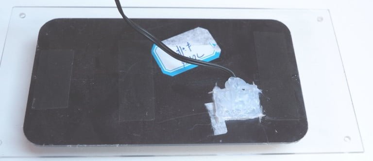
Solar panel should be mounted on some pice of plastic and secured with glue to allow operation in different weather conditions. The perfect angle towards sun is 45 degrees.
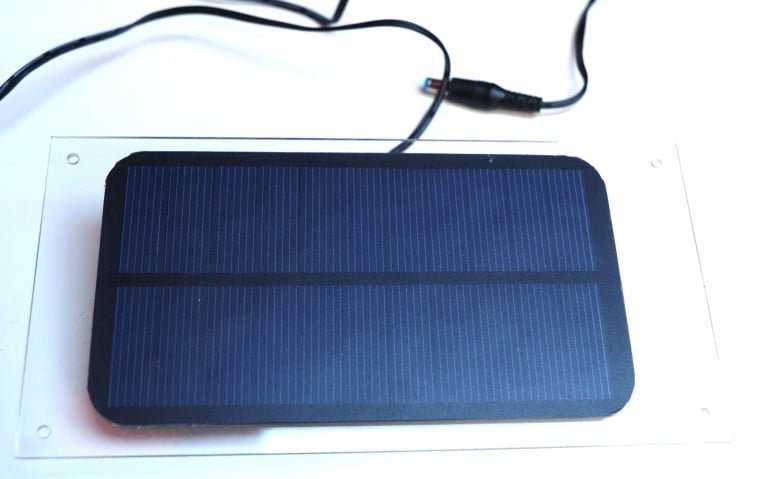
Gluing the panel (I know – lousy job here…):
And then we connect it to power back charge controller via USB:
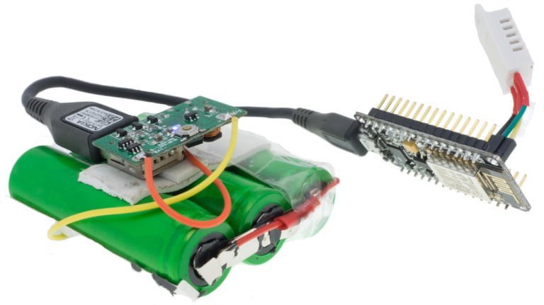
Above you can see the next version of this project – moving to more advanced firmware and hardware – the ESPEasy on ESP-12E using Amica Board with +5V VCC.

This work is licensed under a Creative Commons Attribution-NonCommercial-NoDerivatives 4.0 International License (c) 2014-2024 Łukasz C. Jokiel, [CC BY-NC-SA 4.0 DEED](https://creativecommons.org/licenses/by-nc-sa/4.0/)