Power Supply for Raspberry Pi, Orange Pi or ESP8266 – Xbox 360 PSU Modification
Proper supply of power is a very important part of our SBC (Small Board Computers) projects. Power supplies with too low current efficiency, instability and lack of filtration – often lead to accidental resets, lack of sensor readings or simply unstable behavior of SBCs. One of the solution is to modify the power supply from Microsoft console – XBOX 360.
WARNING: We will work with high currents and high voltage, which requires basic knowledge of electrical engineering. The author is not responsible for accidents and everything you do – you do at your own risk.
What will you need?
Hardware:
- Power Supply shipped with XBOX 360 – it will be permanently modified to suit our needs. You can find one for few $ on popular online auction websites.
- DC-DC Step-Down converter. The XBOX 360 PSU has 12V output. This allows it to be used in some projects directly – powering cameras, fans, however SBC usually operate at 5V and some ESP8266 at 3.3V. We can use converter based on LM2956 chip with volatage output regulated by potentiometer (small “gold” screw) to the desired value, while maximum current is at 2A which is more than enough for most SBC
- soldering iron
- voltmeter (multimeter/multitester)
- heat-shrinkable tube or insulation tape
- wires for 12V devices – i.e.: from broken PSU’s
- small PVC junction box
- electrical connector
- jumper cables, USB cable with micro USB connector
- OPTIONAL: barrel connectors, molex etc.
Power supply modification
Why the XBOX 360 power supply unit? It has a lot of perks:
- great output stability
- current efficiency
- overall efficiency
- additional protection
- internal cooling
- cheap (second hand)
ATTENTION: All work is done with 230V AC POWER OFF. To illustrate the modification process – some photos are done while power is connected to the power supply, which I do not recommend!
We shall start our modification by removing the connector that is attached to XBOX 360:
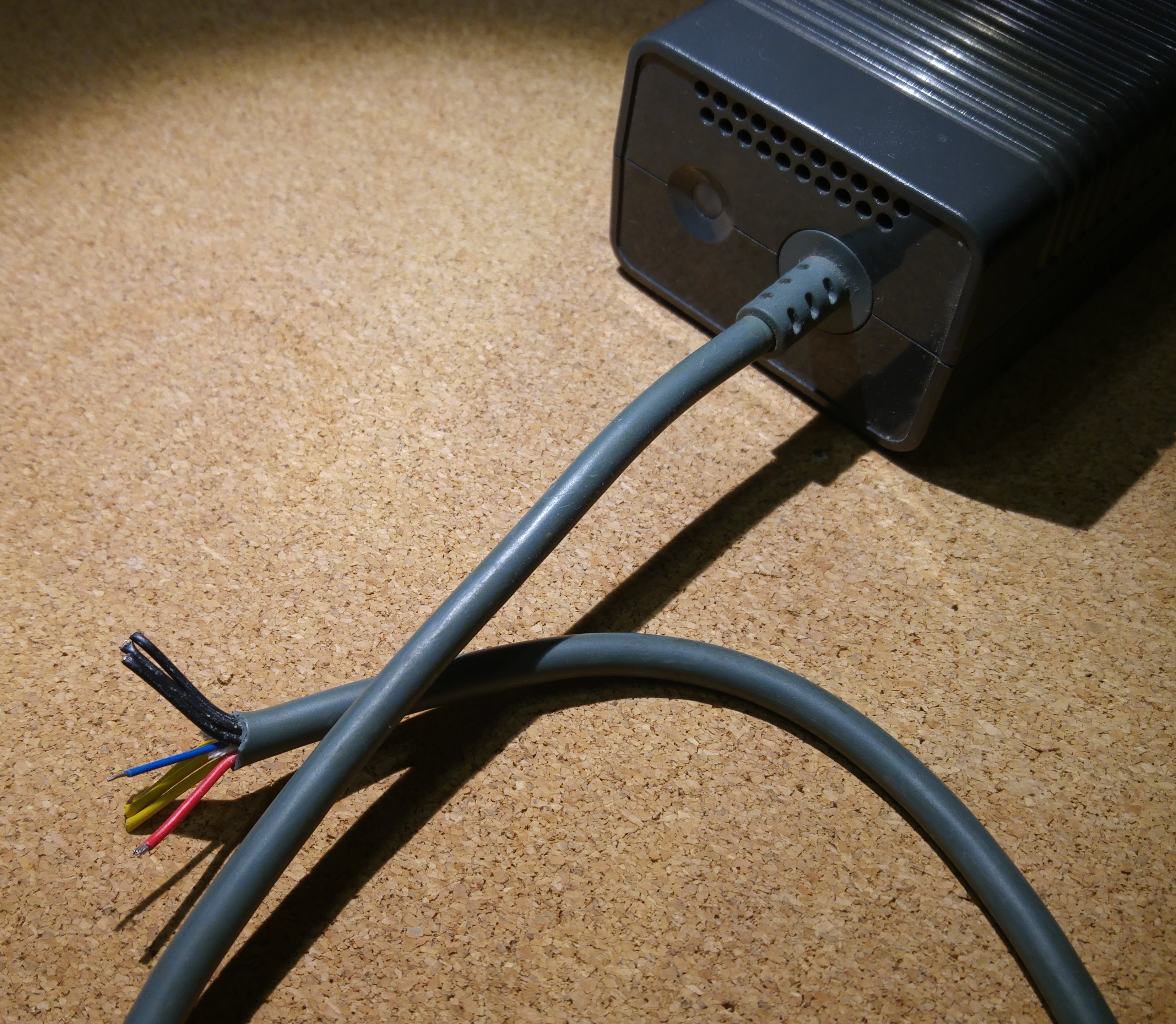
We can see three black wires, three yellow wires – which are of our interest – yellow is 12V and black is GND. Also blue and red (+ 5V), which we will deal with first.
The XBOX has a special protection feature – until it there’s no receiver on the red line – it will not work – and it signals it with orange LED:
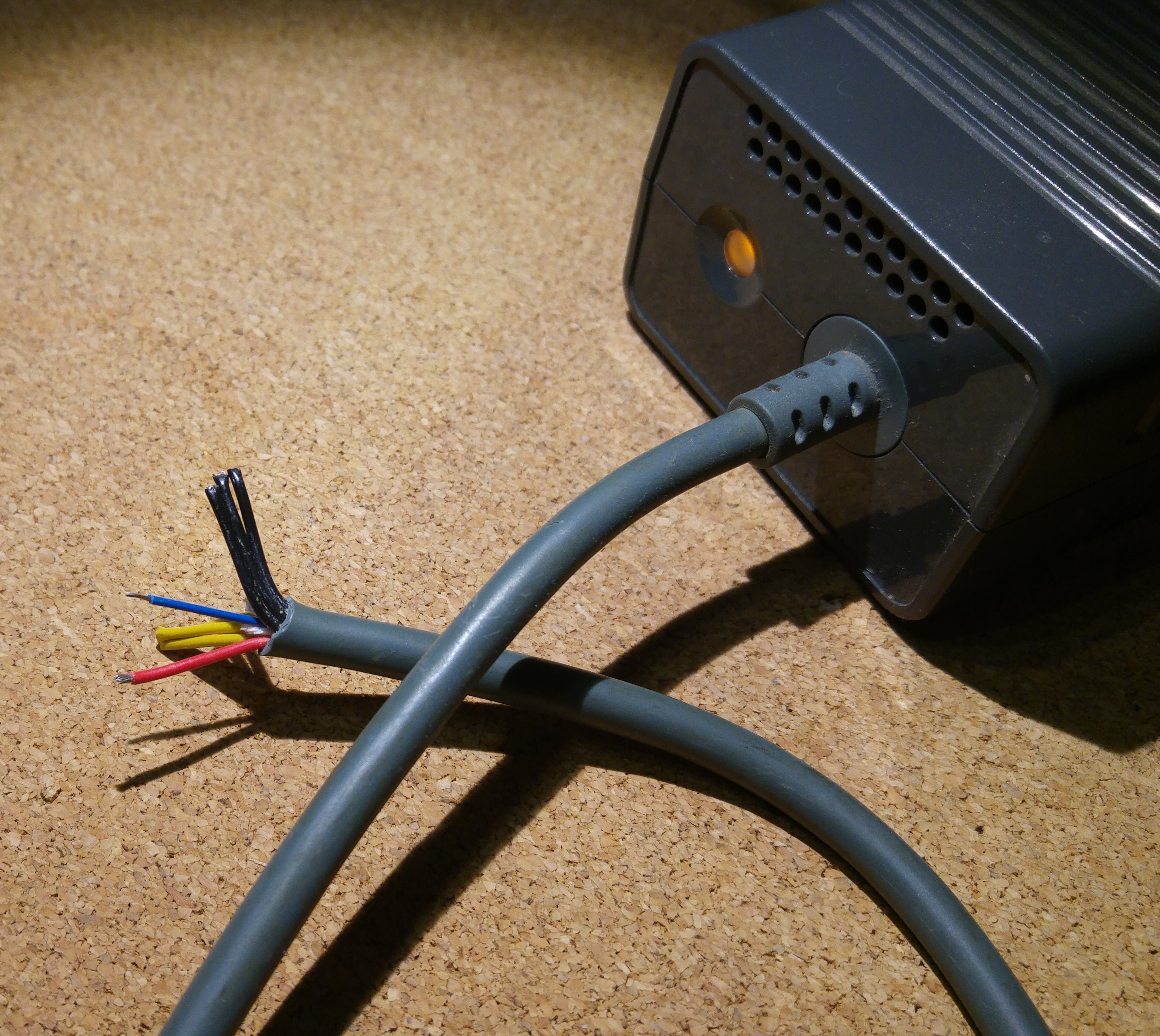
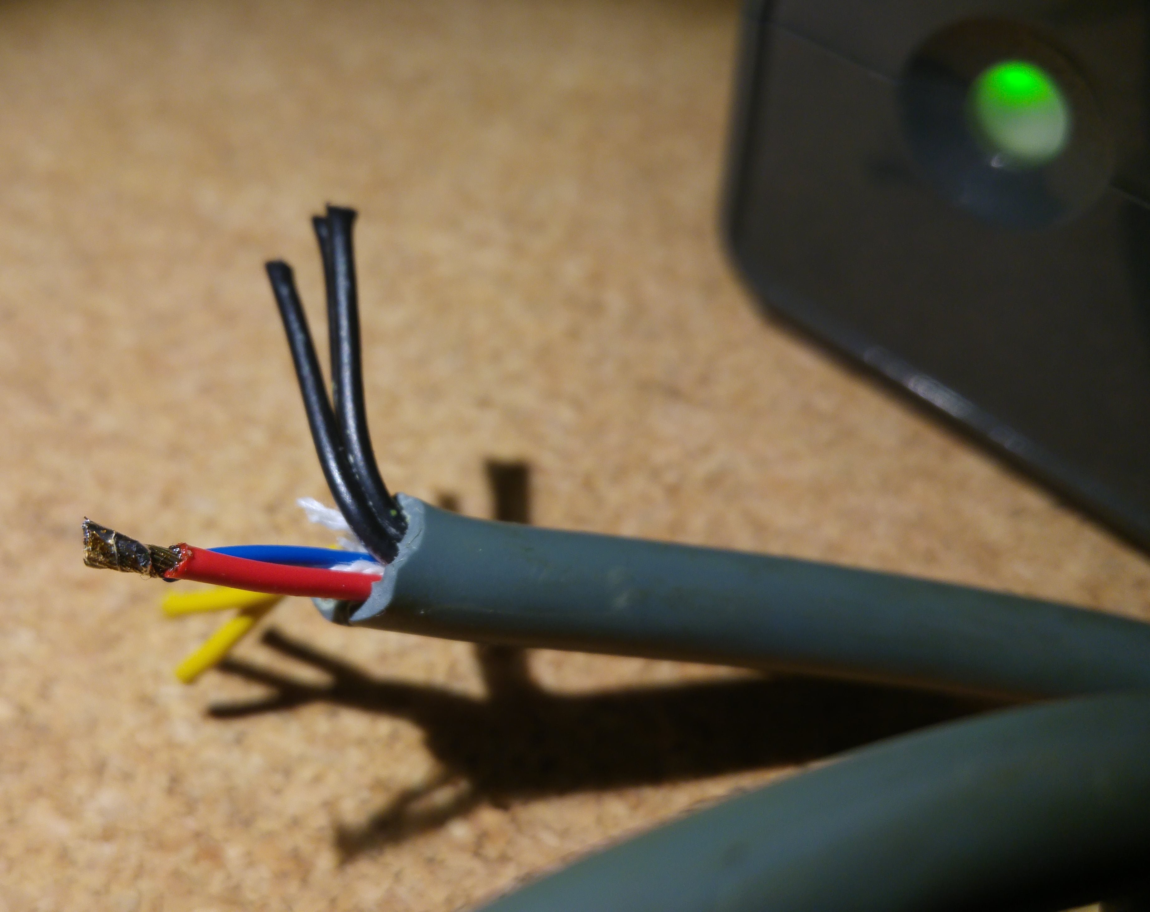
The red and blue wires are 5V/1A, but we will not use it – they should be wired together. Alternatively, you can connect any device that will, for example, in addition to the LED signaling – tell you that the PSU is OK. Let’s solder’em together:
Next put on heat-shrinkable tube or insulation tape:
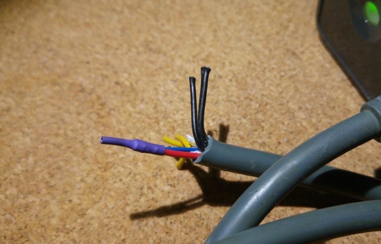
Now, bundle together and solder three black cables and – also bundle together yellow with yellow cables. As a result, we get two single cables – yellow and black. Next do the same with output cables intended for devices: 12V:
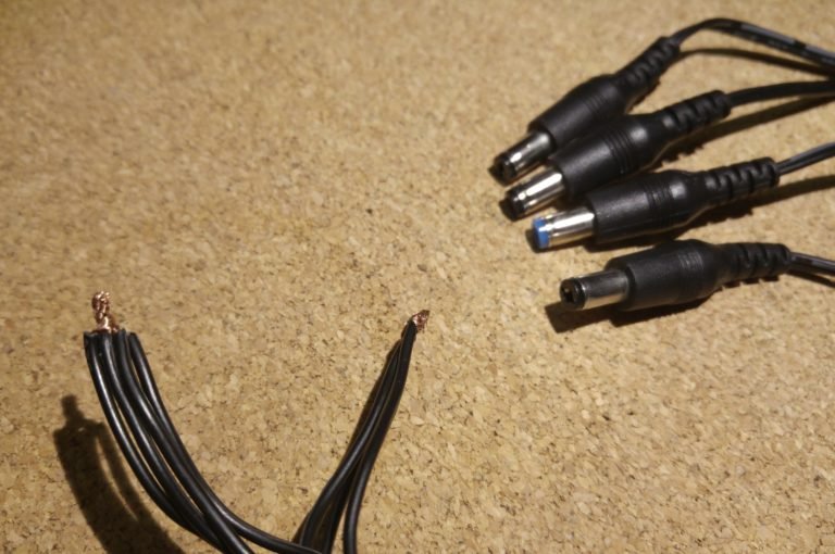
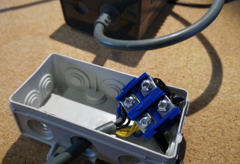
Solder them and put it all into electrical junction box. Caution: the 12V cables have the polarizastion distigushed by the color – white stripes on the black cable denote “+” and full black “-“. Connect the black to black and yellow to black with white stripes:
Time to test out setup – check using the multimeter if there is a short circuit between cables (the “diode”test). If it’s OK – turn on the power supply. If the LED is lit green – verify that the connected 12V cables have the correct polarity – “+” in the center, “-” outside. Then we plug in our DC-DC step-down converter – here I use version with input and output voltage measurement display:
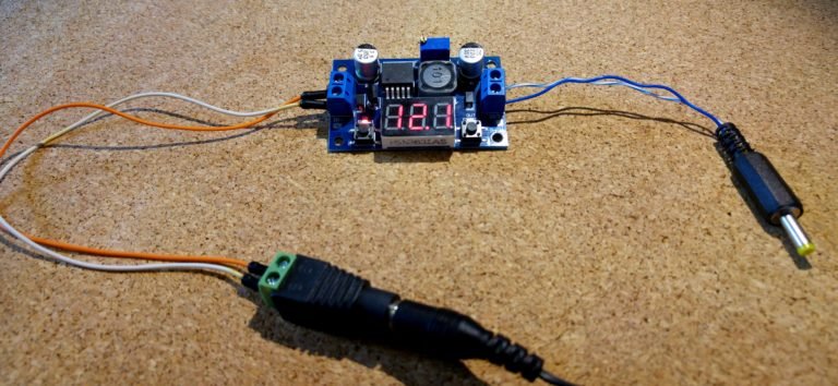
It’s 12.1V so nearly perfect. Set the output voltage with Philips screwdriver and verify that it’s at 5V if so – connect your SBC:
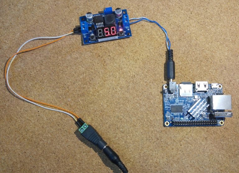
Such setup has been powering network gear, SBC, fans and lightning for over a year in my small ‘server’ room.
That is it!

This work is licensed under a Creative Commons Attribution-NonCommercial-NoDerivatives 4.0 International License (c) 2014-2024 Łukasz C. Jokiel, [CC BY-NC-SA 4.0 DEED](https://creativecommons.org/licenses/by-nc-sa/4.0/)