Atari ST/STE/MEGA ST/STE – connecting to a VGA monitor in color mode
The Atari ST/STE/Mega ST/STE computers had dedicated monitors to support the graphics modes that were implemented by the engineers who left Commodore with Jack Tramiel in 1984:
- mono – black and white – 640×400 resolution, 35KHz horizontal frequency, 71Hz vertical frequency – which is available on most VGA monitors
- color – standard 16 colors from a palette of 512 (9-bit) or 4096 (12-bit) on the STE – resolution was 320×200, horizontal frequency 15KHz, vertical frequency 50 or 60Hz, which is a bit of a problem these days.
-
Since we are going to deal with color mode today – we first need to make sure that we have a monitor that supports horizontal frequency (H) of 15kHz (15.4kHz). Fortunately, they are still available and are usually LCD monitors, I personally use an NEC AccuSync 51V (a small LCD monitor with speakers) and a 17″ NEC 1970Nx(p). A huge list of compatible monitors is kept at: https://15khz.net/
So let’s get to it – let’s connect the Atari ST!
What will we need?
- DIN13 plug – because it is still used for CD changers – it is easily available, it is responsible for connecting the cable on the Atari side.
- VGA cable – preferably 1.8m possible with ferrite on one side (ferrite looks like a cylinder applied to the cable)
- soldering iron – the cheapest model with temperature regulation will suffice – I recommend 270C, which does not cause the flux to evaporate too quickly
- three 47Ω (47R) 0.125W through-hole resistors – these are even smaller than the ones usually used in projects
- multimeter with diode test option – to look for signals. When you short the tester – the multimeter should give a squeal
- heat-shrink tubes
- compatible monitor – remember VGA with 15.4kHz H
Let's do it!
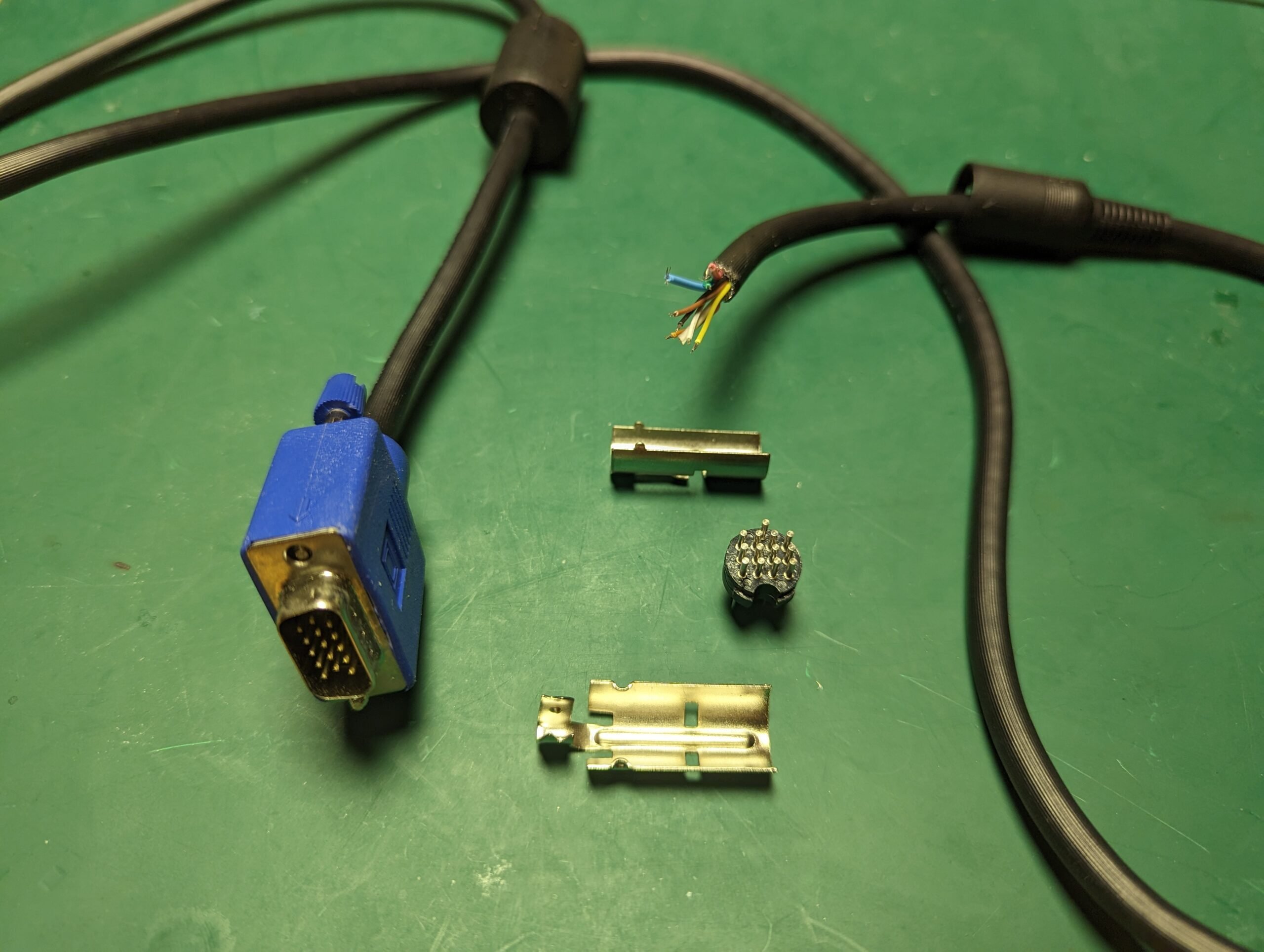
First, we cut off one of the VGA ends and expose all the cables:
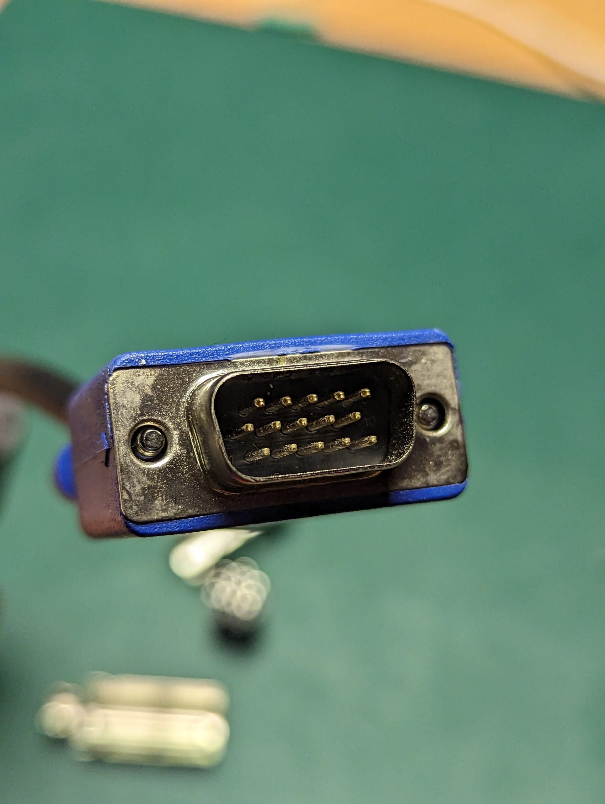
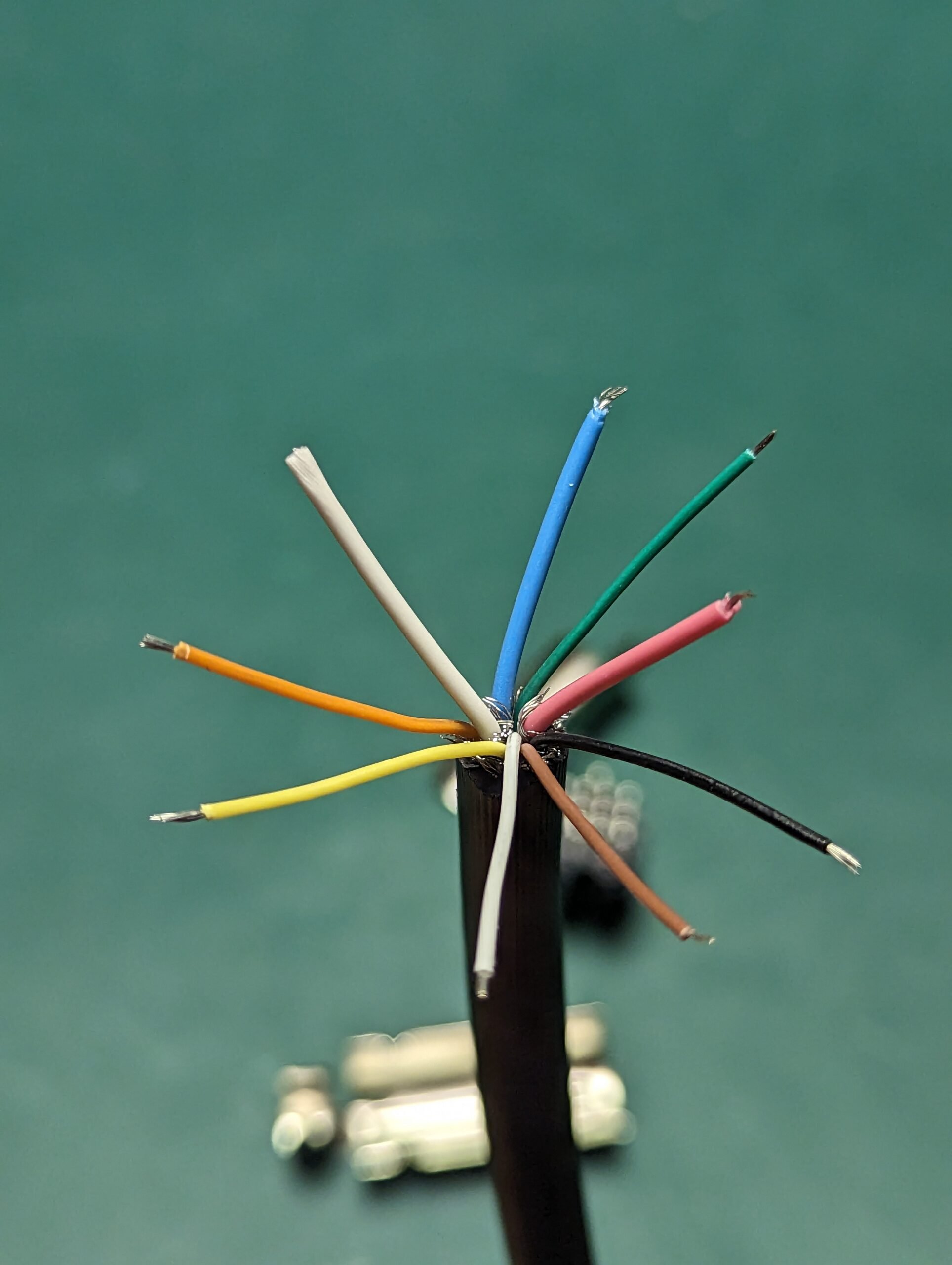
Next step is to look for signals – we need R,G,B and V-SYNC – H-SYNC and also ground. Using the diode test with multimeter we can easily find the colors according to the diagram:
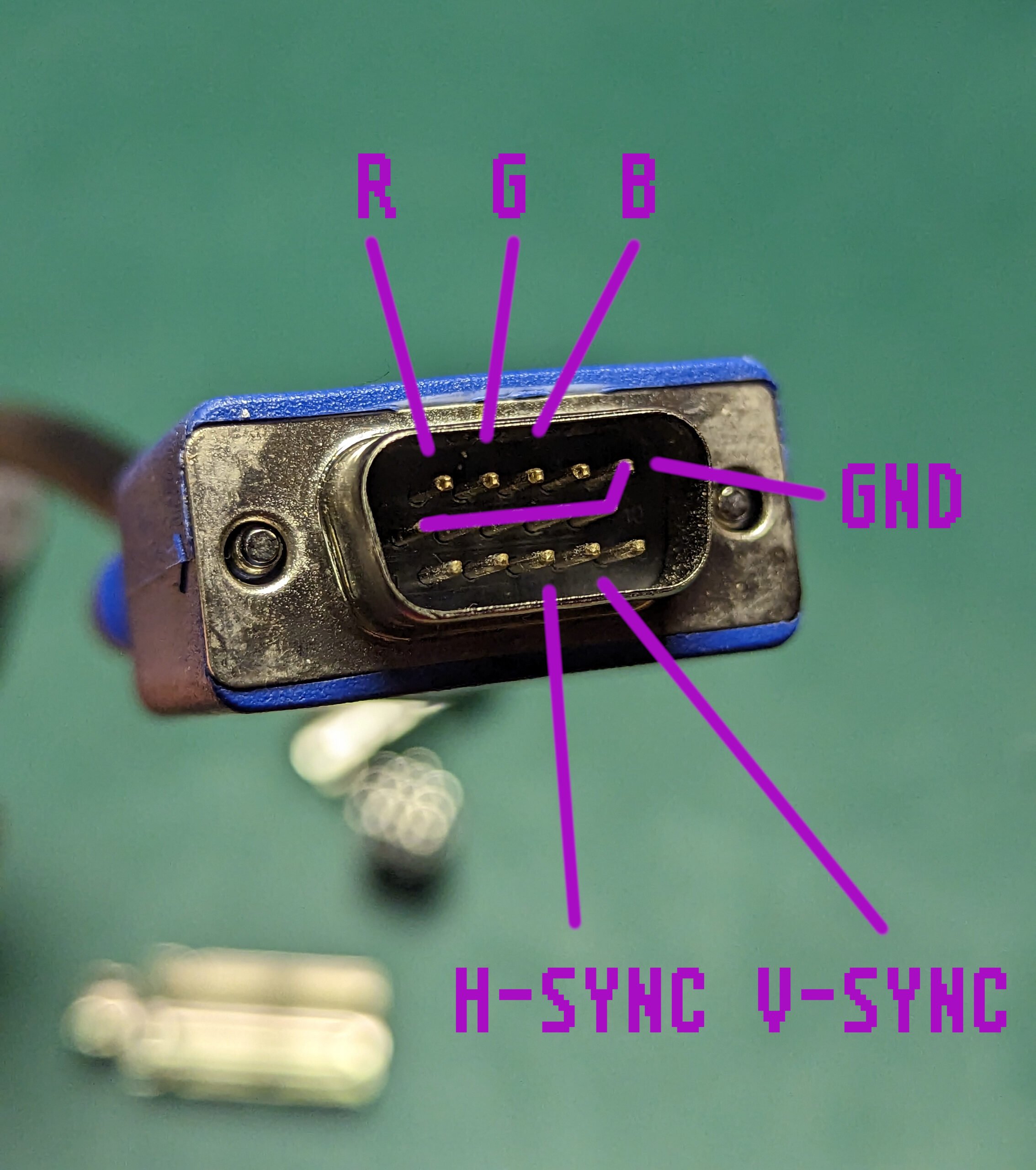
As you can see, the R,G,B signals of the VGA plug are at the top row, GND in the middle row, and horizontal and vertical sync in the bottom row.
What remains to be figured out now – and let’s look at the soldering side of DIN13 (the one where pins are shoter) where to solder our colorfull wires:
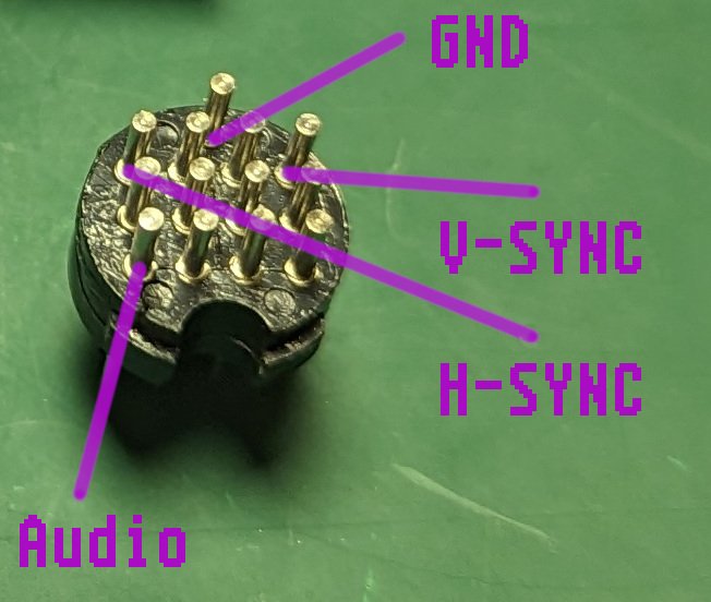
OK, lets start – locate GND, Audio and sync, but don’t solder them yet! We need to solder R,G and B first:
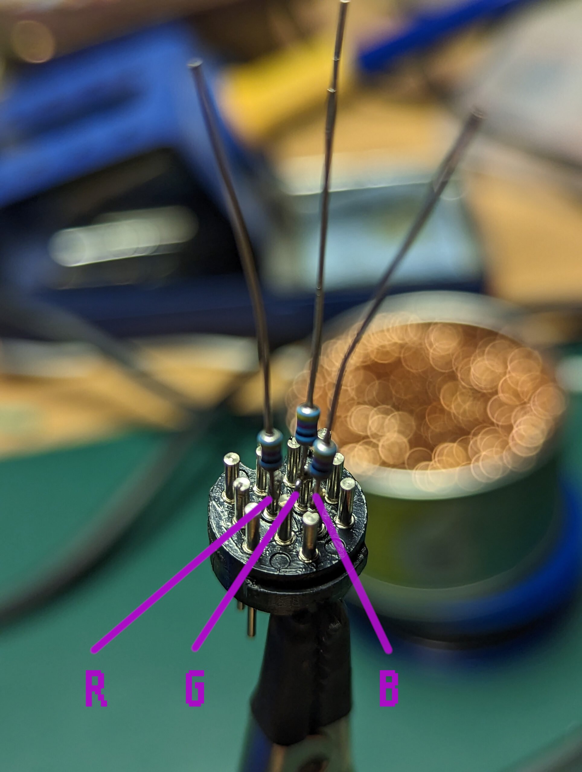
Here is an alternate view to better locate the pins:
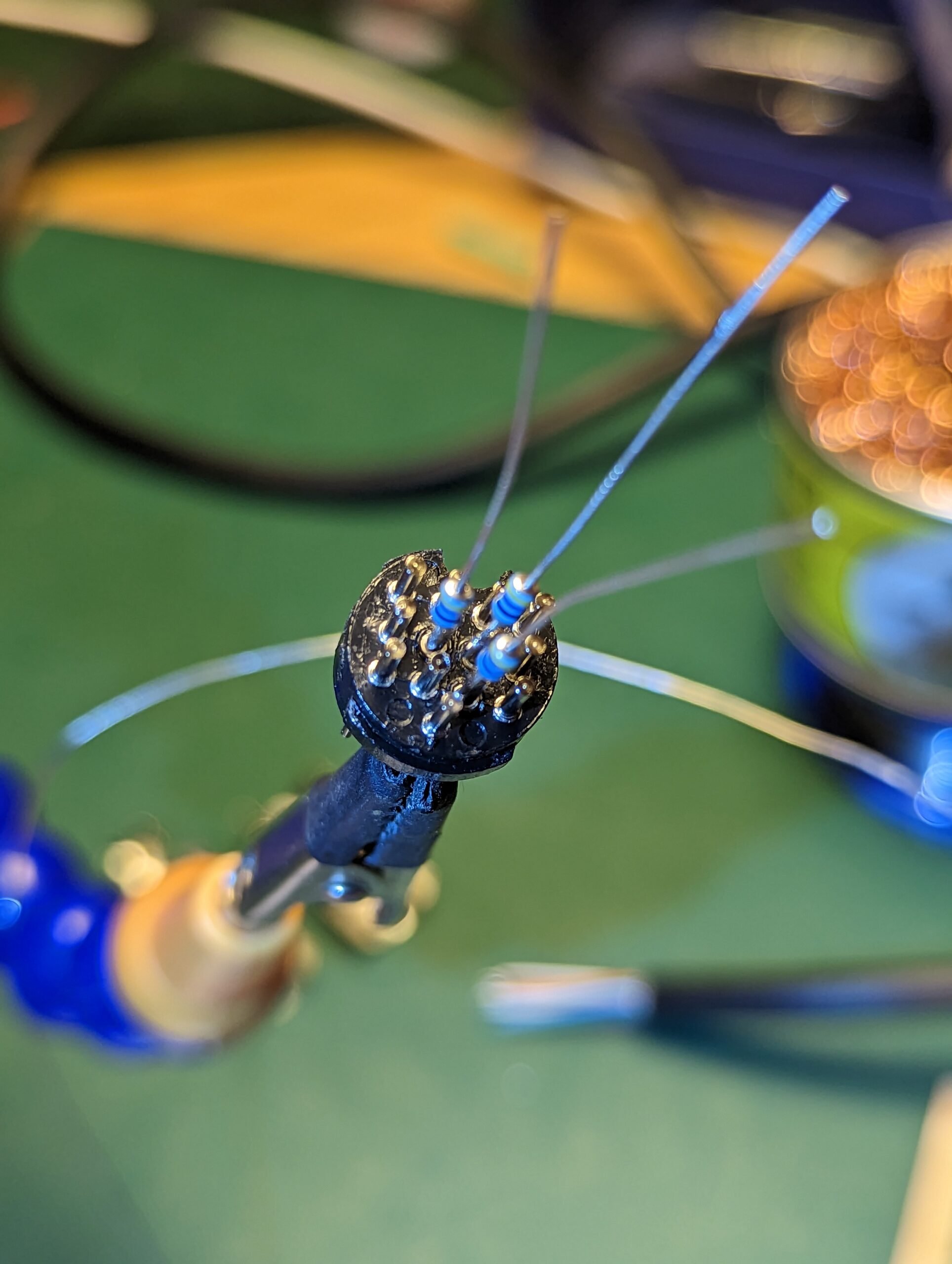
As you can see we solder the resistors here – 47R in L shape. Let’s add heat-shrink tubes and follow up with remaining signals.
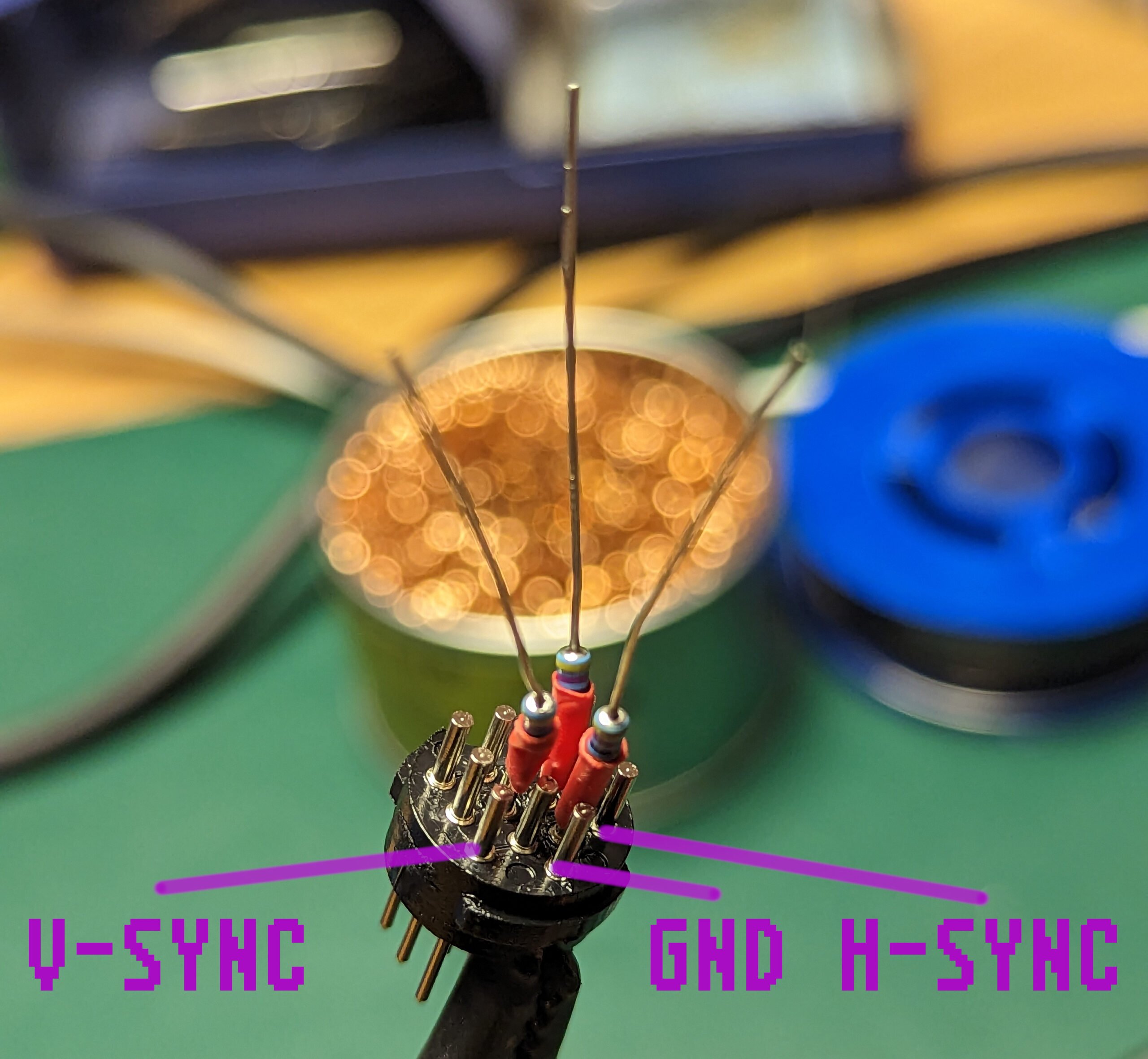
Other signals as you can see are on the edges… Let’s cut the resistor legs and solder R, G and B!
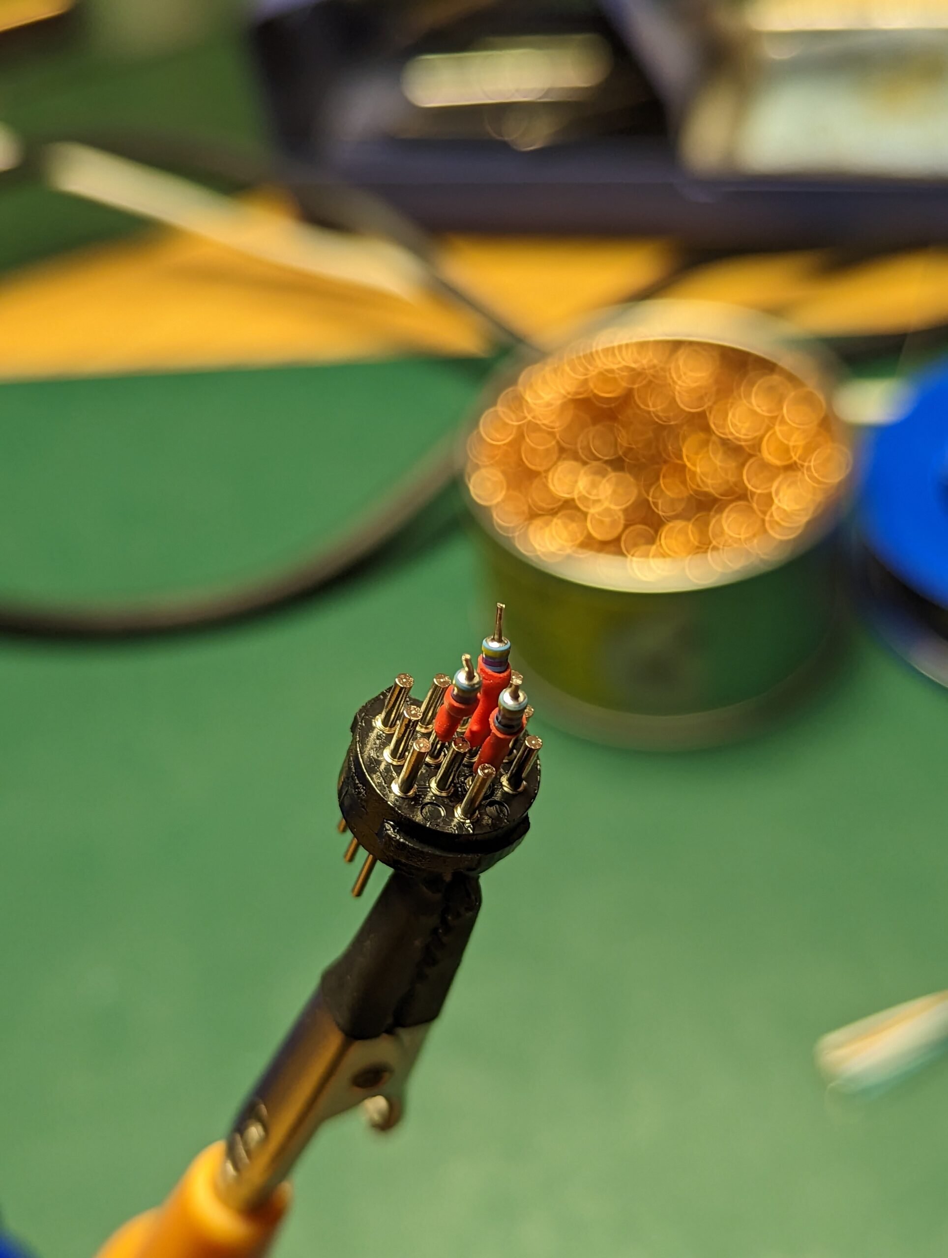
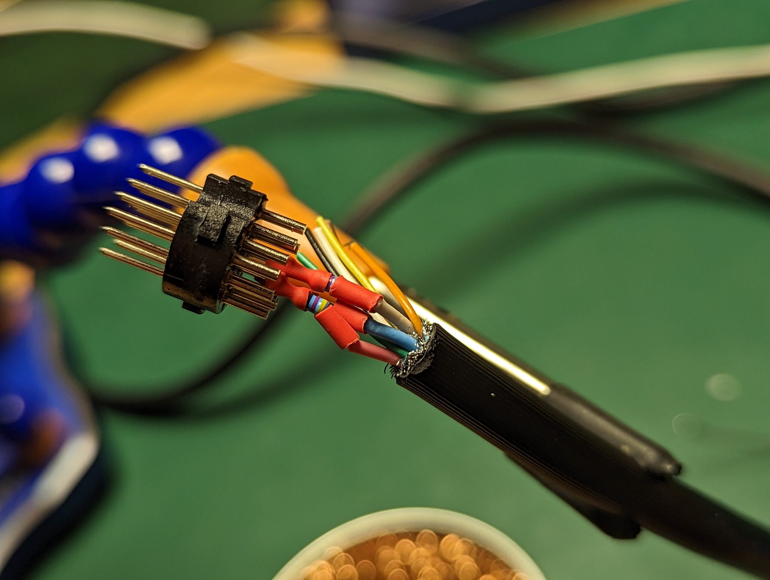
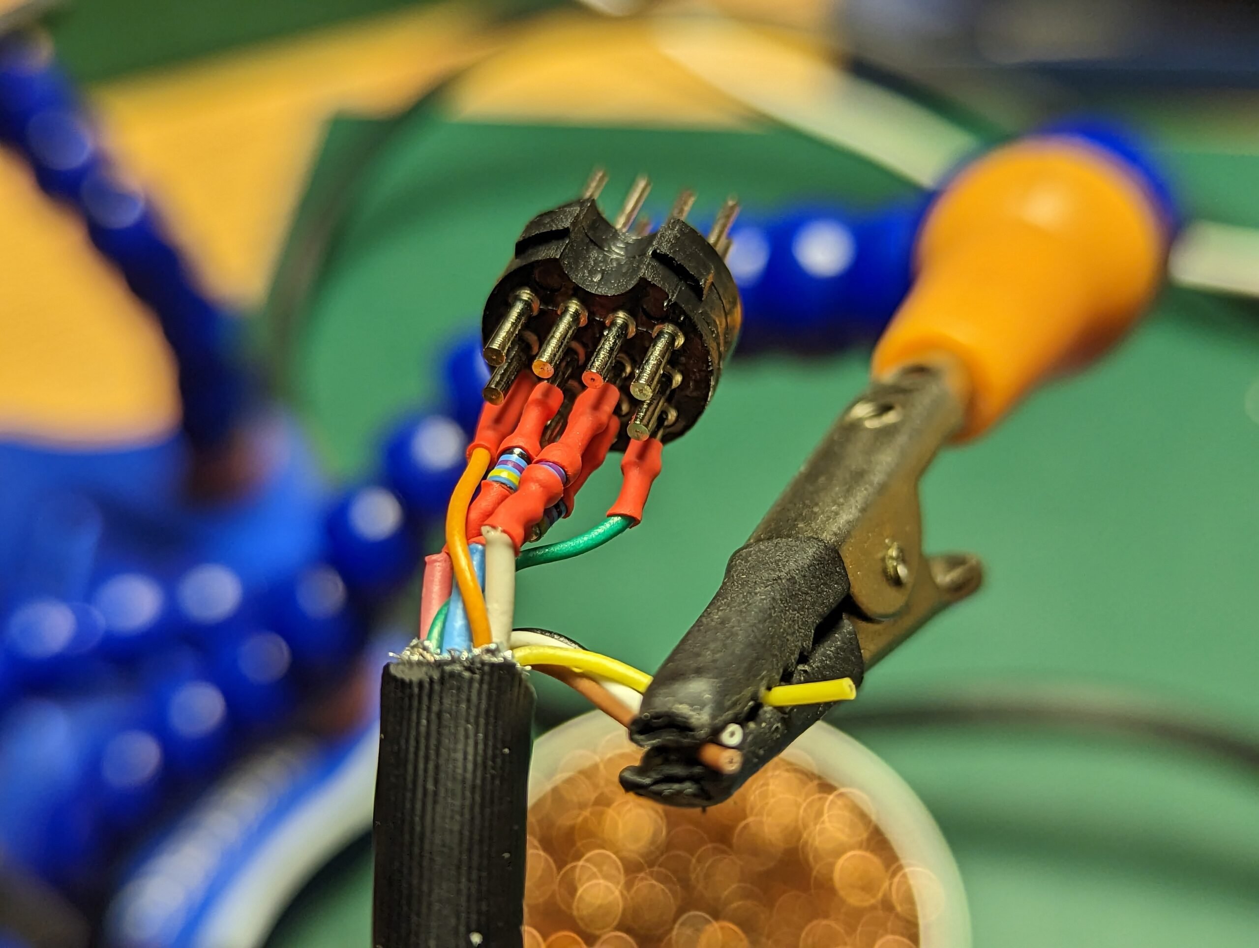
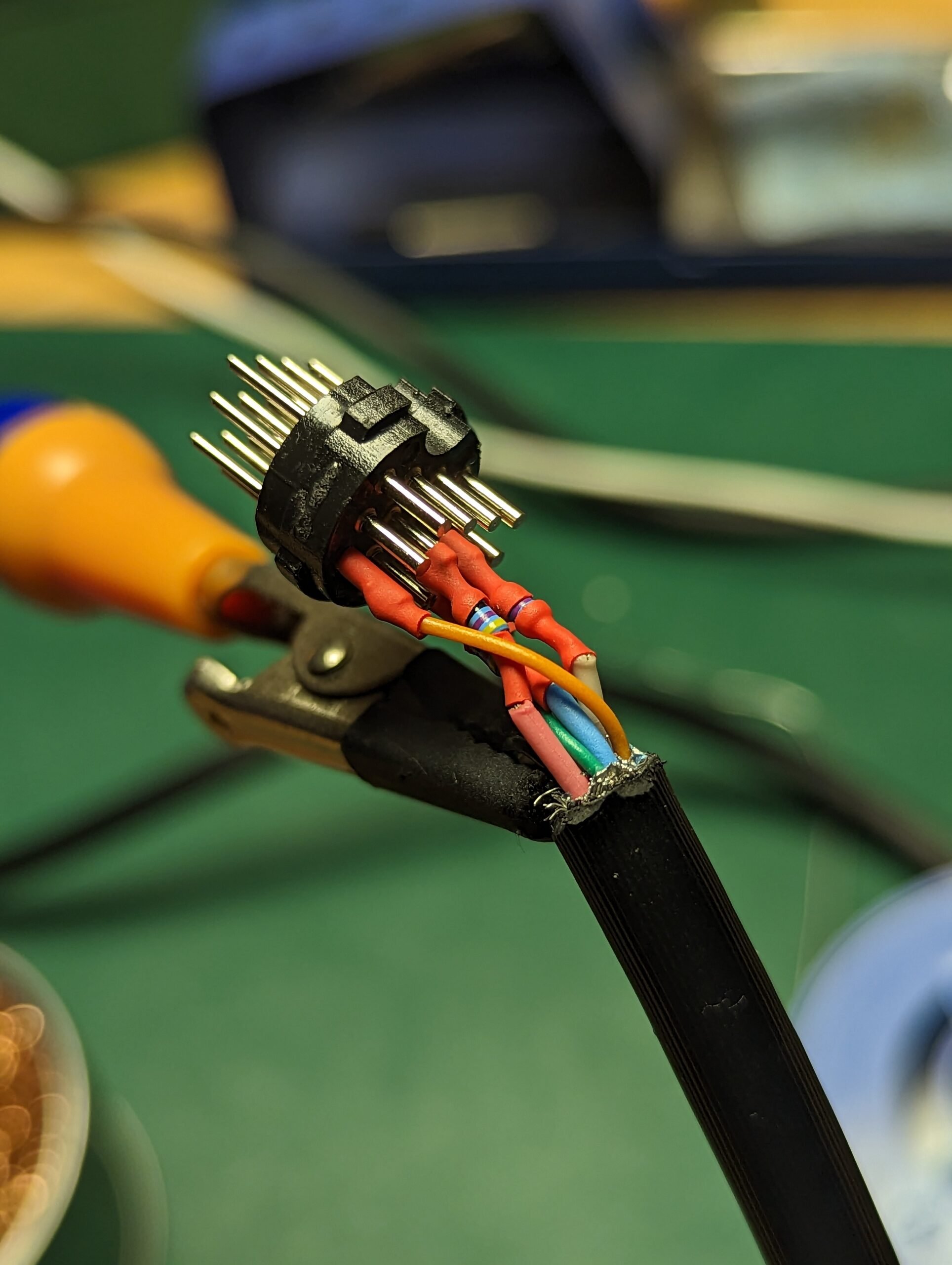
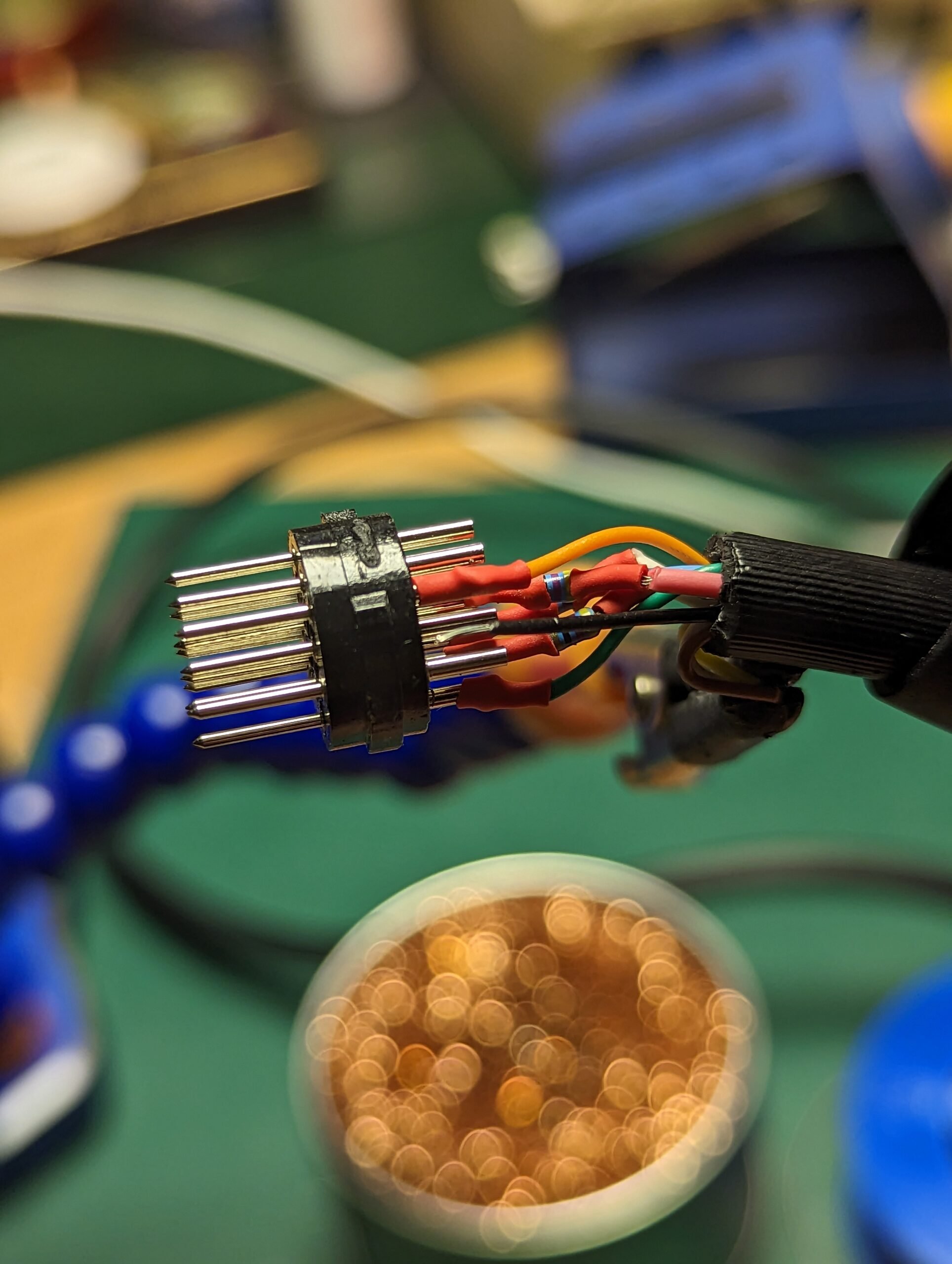
Sound – requires sloldering not only the audio pin also GND – lets use extra cables and get them outside. We solder both signals to, for example: jack socket – this is just mono sound.
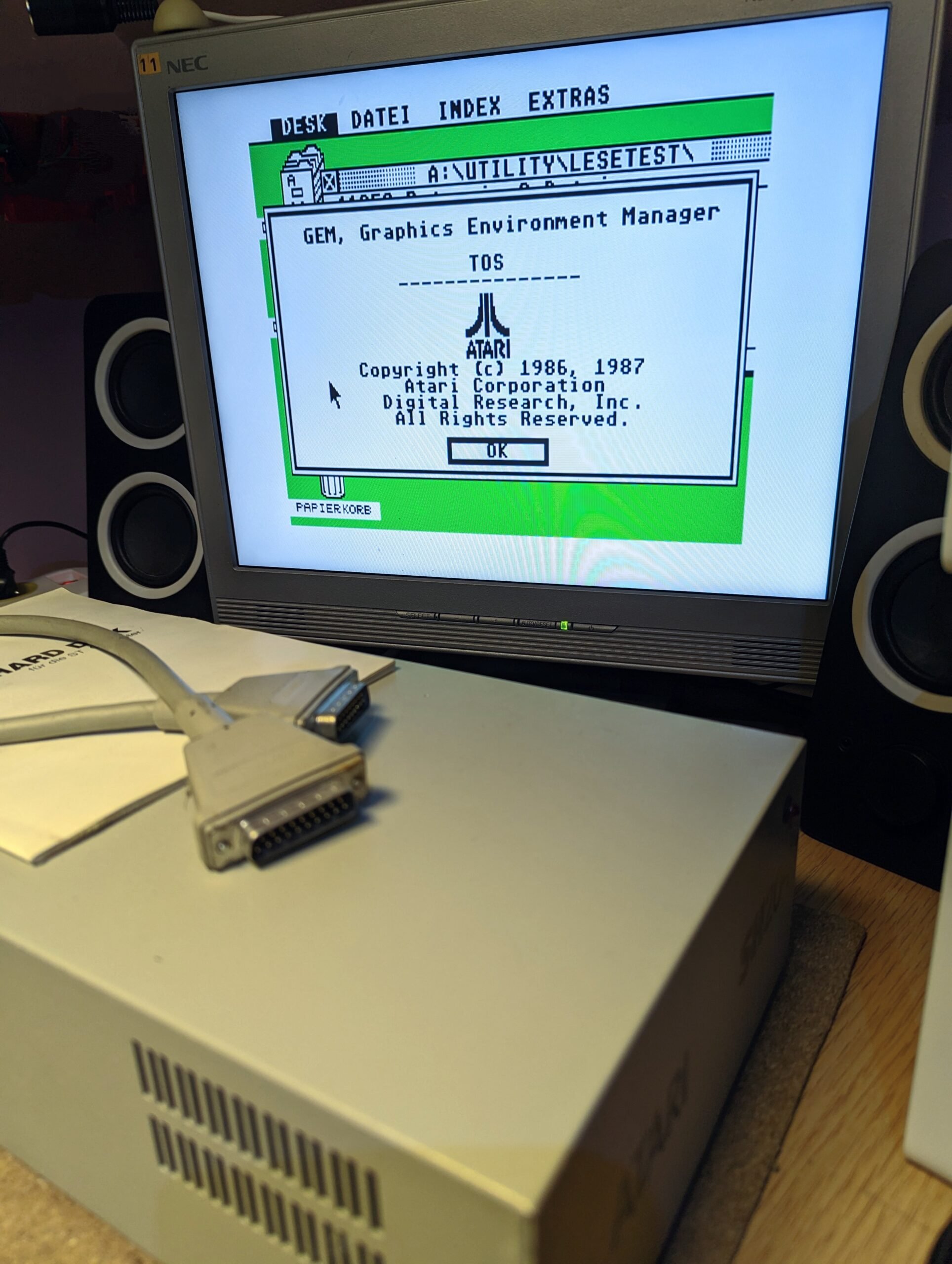
Done! Let’s test our cable in Atari ST/STE/Mega ST/STE!

This work is licensed under a Creative Commons Attribution-NonCommercial-NoDerivatives 4.0 International License (c) 2014-2024 Łukasz C. Jokiel, [CC BY-NC-SA 4.0 DEED](https://creativecommons.org/licenses/by-nc-sa/4.0/)