Atari ST/STE: hardware modification – perfect HDMI image output thanks to the RGBtoHDMI project and Raspberry Pi Zero
RGBtoHDMI for Atari ST/STE is a great project to add modern video to an old home computer. How old? Atari ST is almost 40 years old (today: 37), based on a 16 /32 bit MC68000 processor with 8MHz clock and a maximum of whole 4MB RAM. Nowadays, almost every new micro-controller is much faster and more capable, but this is not what makes it iteresting – that would be the nostalgia. Thanks to this “noSTalgia”, new versions of games are still created today – i.e., Lotus Turbo Challenge
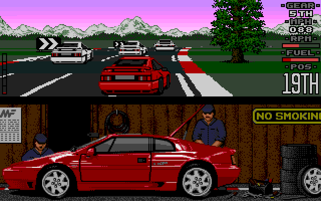
re-make that uses the additional capabilities of the updated hardware in Atari STE (blitter, sound) or projects aimed at modifying the old computer to make it compatible with today’s standards – ACSI hard drive emulators or the project discussed here RGBtoHDMI. The number of devices that are compatible is huge: Atari ST / STE, Atari 8-bit, Amiga, Amstrad CPC, Spectrum, Atom, Dragon / Tandy Color Computer, as well as monochrome output from Apple II / IIe / IIc, UK101, Superboard II , ZX80 or ZX81.
The main goal of the project is to present the image with pixel perfect accuracy with minimal delay – currently about 1/4 of the pivture frame duration.
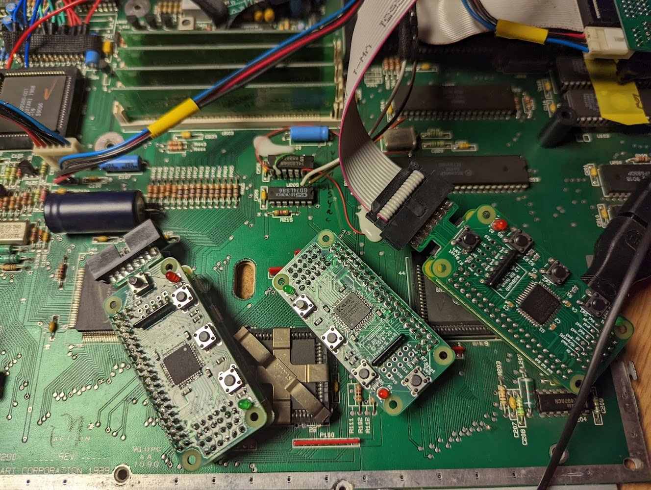
RGBtoHDMI allows for direct digital conversion of the video signal generated by Atari ST / STE and to convert to a format compatible monitors or TV sets with HDMI / DVI input. We are also presented with several options to make the picture/video more in line with what we saw once on classic CRT monitors or televisions.
Project is created by: Holger76 oraz IanSB
What will you need?
-
Hardware:
- Raspberry Pi Zero H (can be version 2 or W) – version H has soldered pins, also the RUN pins.
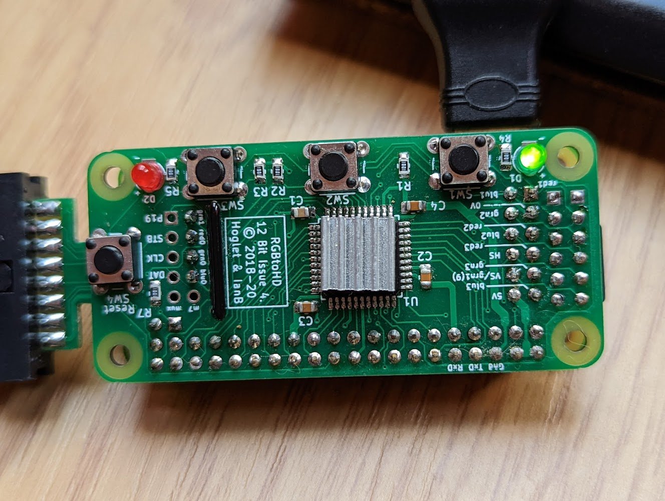
- Skills of soldering small SMD components – 0805, CPLD, or alternatively ordering a ready-made project
- If you decide not to order ready-make boards – and build it yourself – you will need:
- three printed circuit boards (PCB), which we can be order for almost nothing on the Internet
- the first is RGB2HDMI PCB – in the last version of gerber files,
- second is an additional 12 bit extender daughter board, which allows you to download the signal from the computer and output it for better control and ventilation – with ordinary gray tape
- third – for Atari ST: 12-bit Atari ST buffered pickup board, and for Atari STE: 12-bit Amiga buffered pickup board, which needs to be extra modified to work with Atari STE.
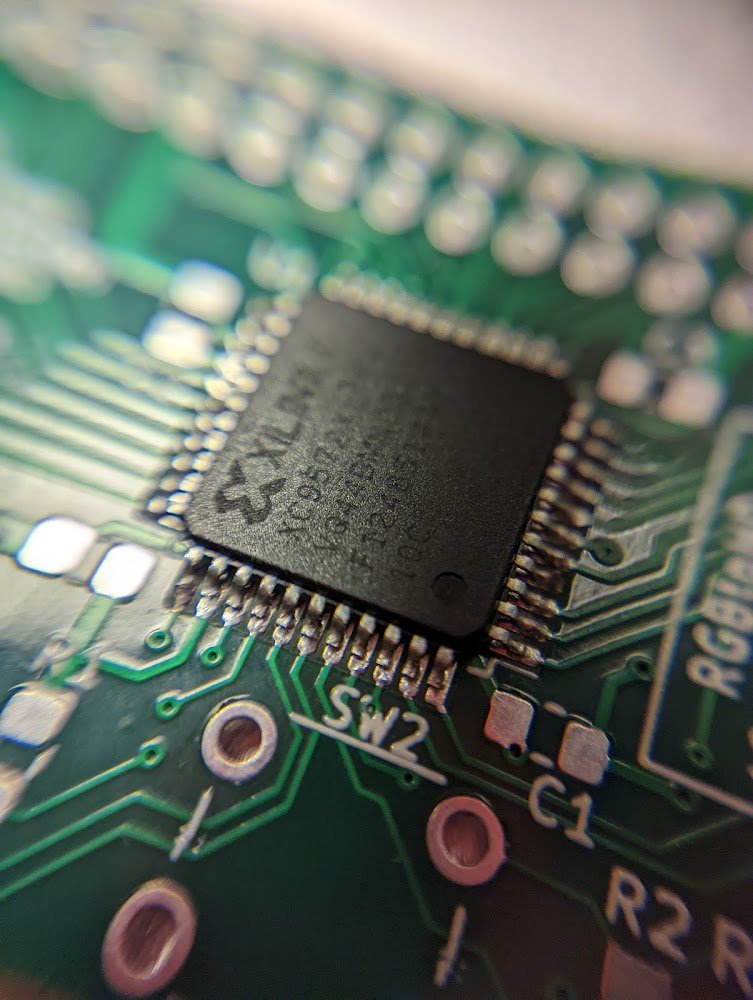
- among other elements – the most interesting is – CPLD AMD Xilinx XC9572XL – 10VQG44C
- in addition, we have several bus transceivers and passive elements – capacitors and resistors, tape, LED, buttons
Software:
- git clone https://github.com/hoglet67/RGBtoHDMI/
- Additional important information is available at: https://github.com/IanSB/RGBtoHDMI/
- Specific software version – preferably from: https://github.com/IanSB/RGBtoHDMI/releases.
- We are currently working with the Beta54 version
Installation in Atari ST – 520ST/1040STF & 520FM/1040FM
Atari Corporation, which has been producing Atari home computers since 1984 – was created from the merger of some Commodore engineers under the leadership of former CEO – Jacek Tramiel. Atari ST (ST comes from sixteen thirty-two is initially a 512kB RAM version (yes, there were also 260ST and even 130ST versions), or 1024kB RAM (1MB) – but we are interested in the ST version or STFM – presence of video signals that are needed to install RGB2HDMI:
On the disc, we need to locate Shifter – that is, the system that is largely responsible for creating the video signal, which is then directed to the monitor output, and in the versions with M in the model name – also to the RF modulator. Additionally, although we do not need it directly – the ST version has the Composite Sync signal, and the ST version with M – the Composite signal.
Why do we use this more complicated system – after all, in the Amiga 500/600 one PCB and RPi Zero are enough! Well, we use both boards to protect the Atari ST and for the comfort of work. On the board connecting the Amiga 500/600 with the RPi, bus converters are installed – also used here to convert digital signals – which in the Amiga or Atari ST have 5V – and the RPi expects 3.3V. This can cause the RPi to overheat – or even physically damage its inputs. In turn, the pickup board for Atari ST is designed to lead the signal outside, the attack to conveniently control the RGB2HDMI buttons and protect the VSYNC and HSYNC generating circuits – because they cannot be connected without separation to achieve the required CSYNC signal.
So we start by unscrewing the screws of the case, carefully, it is fragile and removing the metal screens (pliers!). We can remove the screens permanently, because in the 1980s the American FCC regulator required very low EM emissions from devices, which was only provided by such screens. This is not dictated by health considerations, as the Atari ST emissions do not adversely affect living tissue, but cause interference in analog receivers.
Shifter is on the plate in an additional metal cage, and – if we’re lucky, it is placed in the stand. Open the cage (cover) and remove the Shifter – carefully, of course, in order to gain access to the Shifter’s base marked in blue: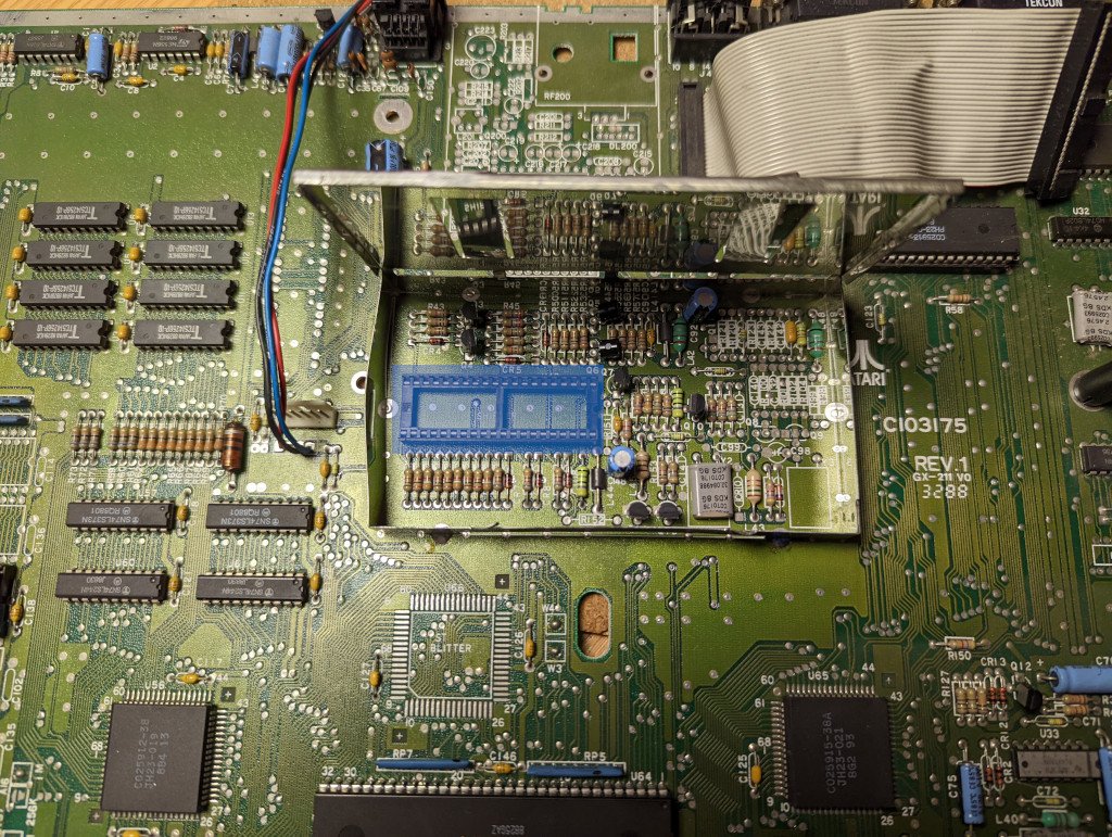
The next step is to remove the metal cage. Usually, this step is optional, but later it may turn out that our signal acquisition board will not fit:
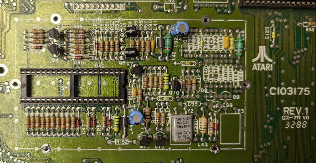
Then install the Atari ST Buffered Pickup Board in place of the Shifter:
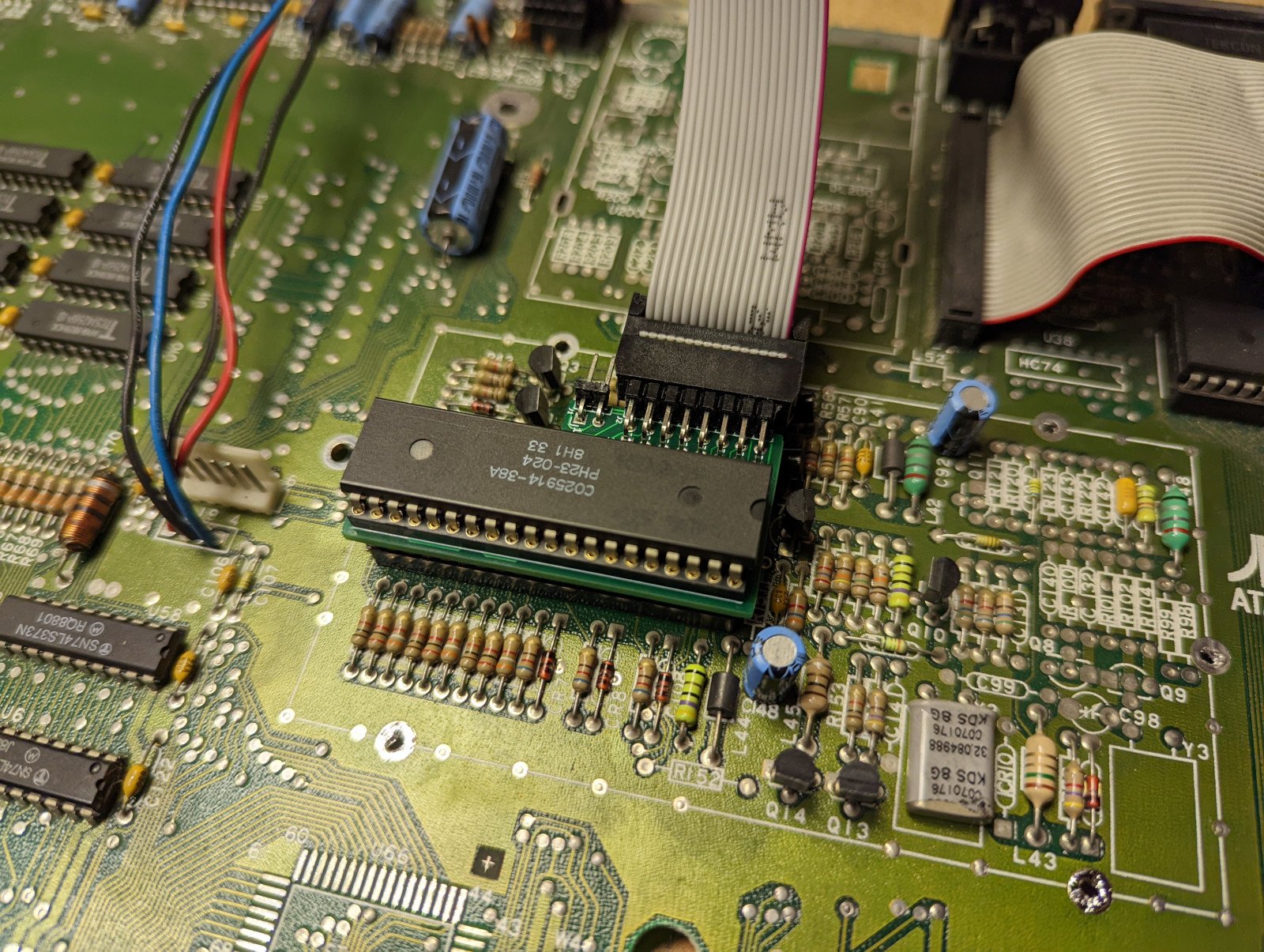
Now we can connect it with the RGBtoHDMI board equipped with a daughter board and RPi Zero, properly positioning the tape connecting the boards:
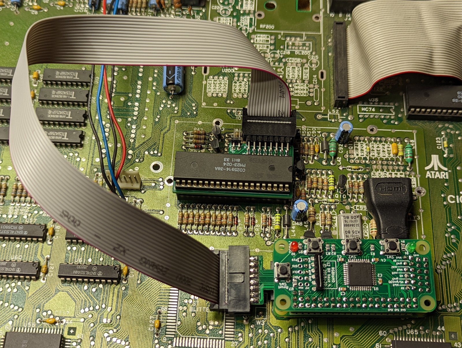
Is that all there is? No, but we’re close. Power for RPi Zero that we connect to the board will be taken from the Atari ST. We have to solder two pins – which will connect the HSYNC and VSYNC signal from Atari ST to the system. Pickup board is responsible for their proper connection (with galvanic separation).
Where to get these signals – well here we have some options, due to the design of the Atari ST – if we have a modulator, both signals are close to each other above the Shifter:
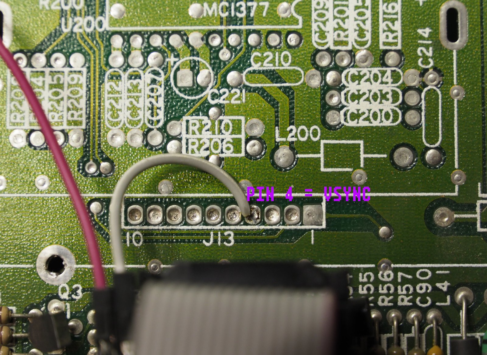
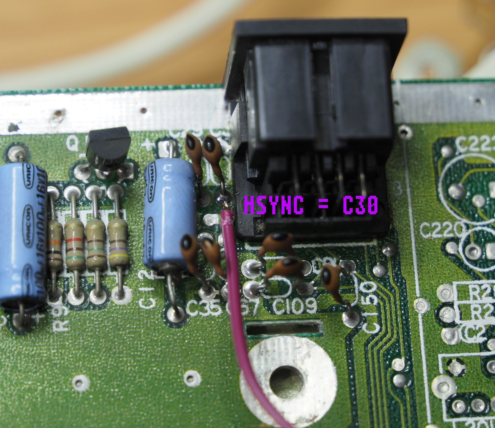
If we have STF – we have a bit longer path:
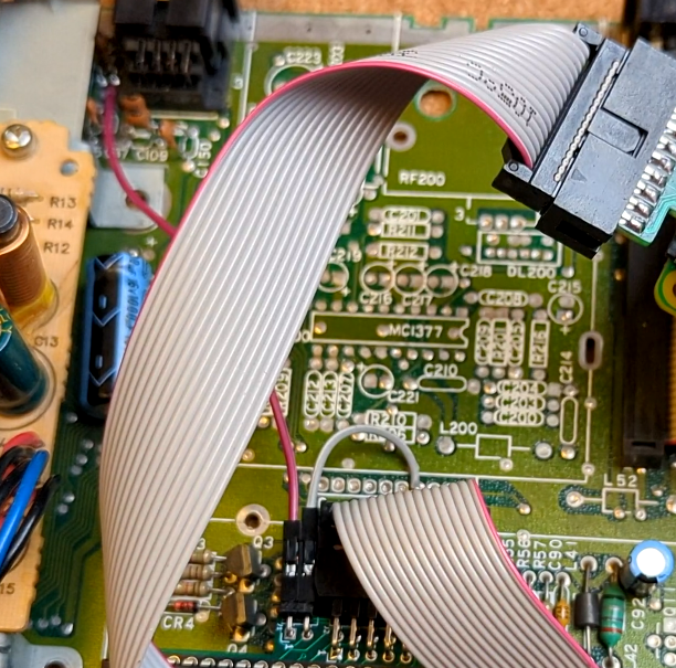
The soldered signals mean that we can connect RPi Zero W to RGB2HDMI (the heat sink on the CPU will not fit!), Place the board in a safe way:
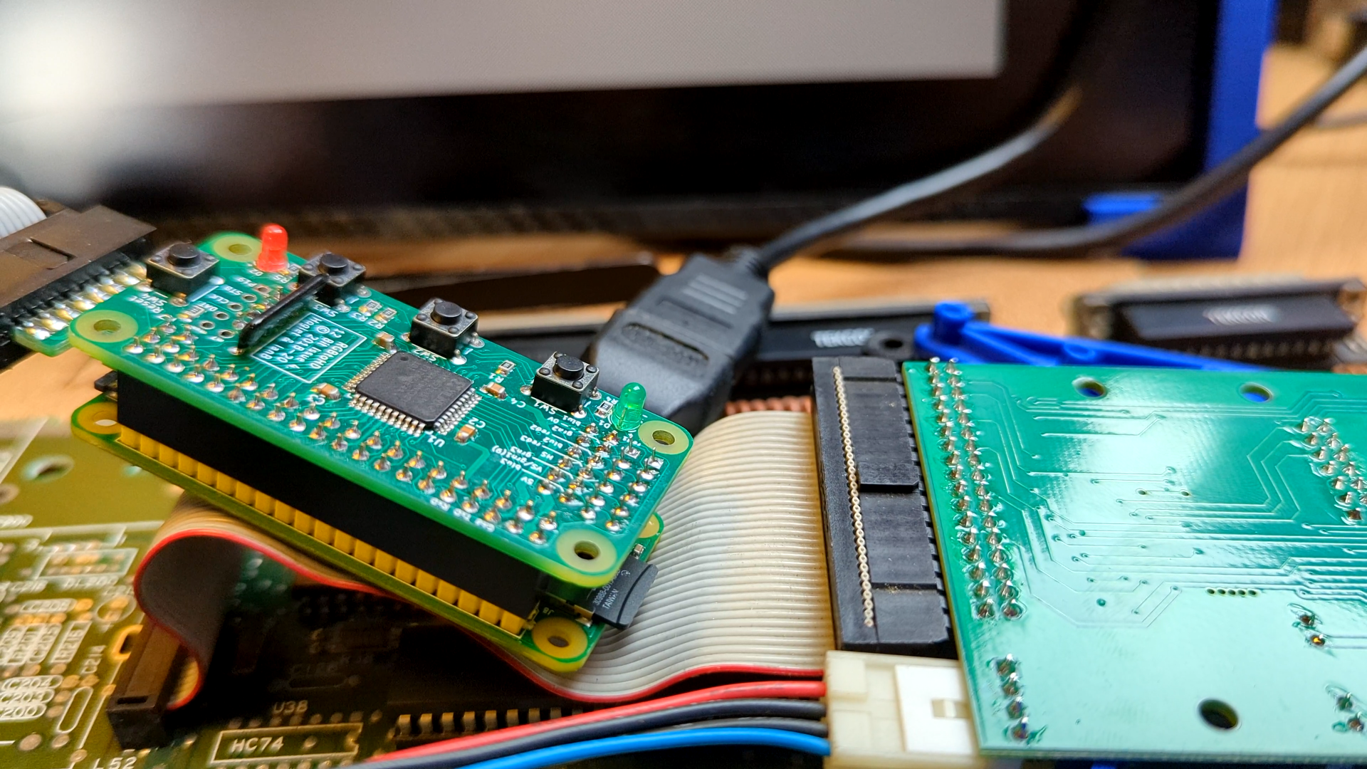
connect a floppy drive or hard drive – or modern versions like here – and a mono monitor or a plug that has mono detection enabled and test!
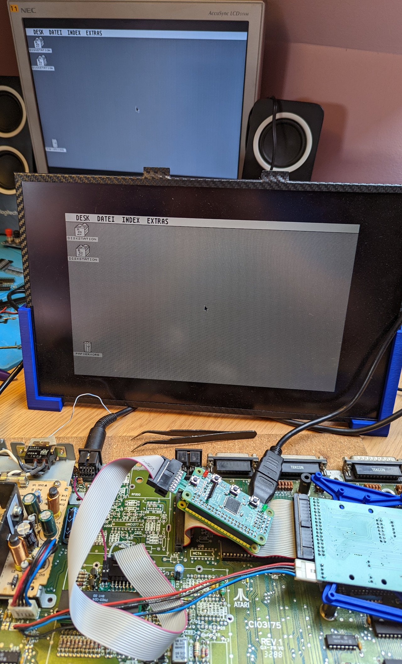
For the low-res / medium-res version – we can connect a color monitor, or not connect at all, Atari ST will then start in color mode by default:
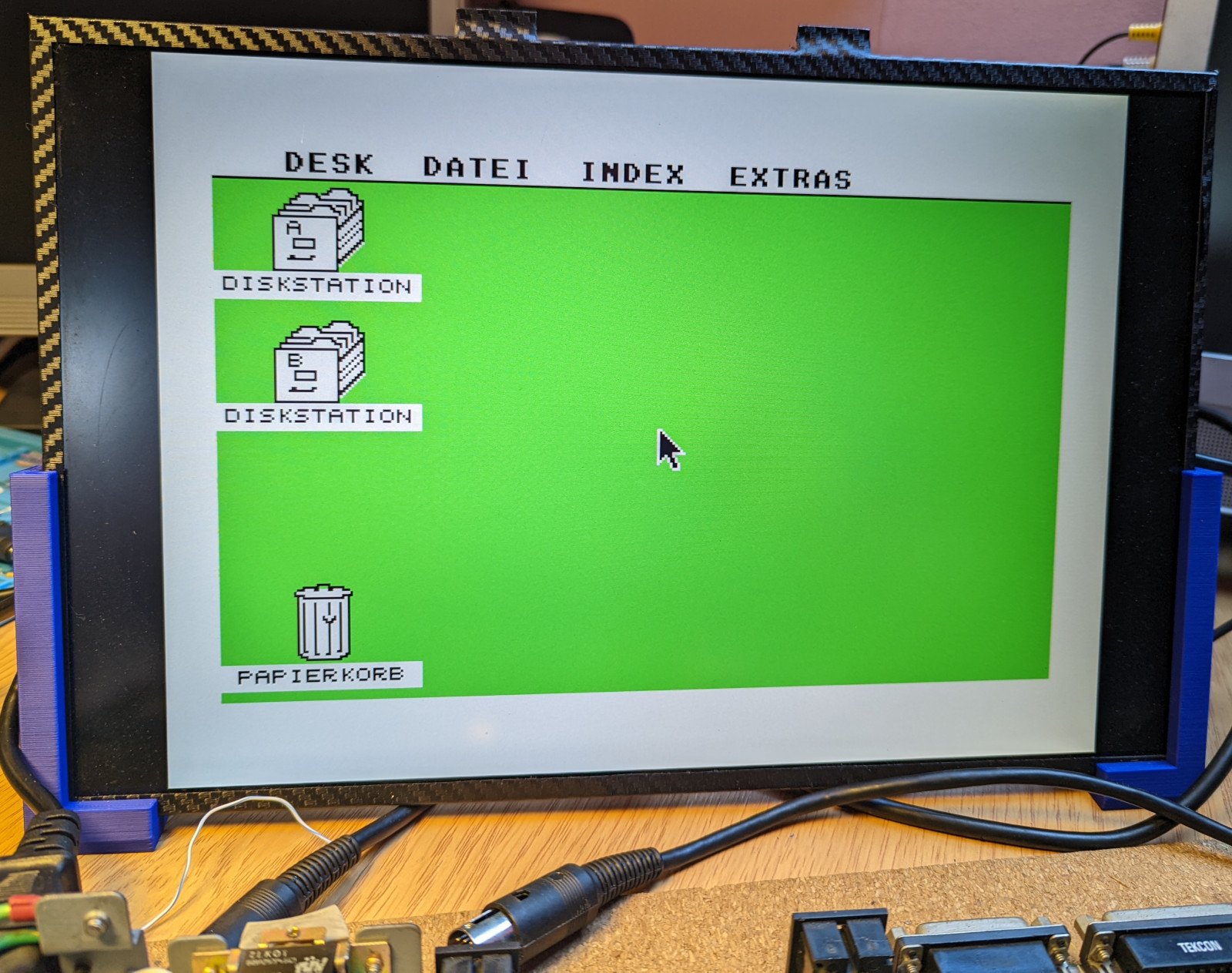
Inne wpisy na temat RGB2HDMI dla Atari ST:
Additional read:
Martin Döring got a version of one of the oldest ST – Atari 260 ST and has described his method as well – check it out, it’s great – more on getting VSYNC and HSYNC
Installation for Atari ST 520STE and 1040STE
This time we need to use a transition/middleware PCB that will collect signals from the STE and pass them on to the main board. For this purpose, we use a slightly modified Amiga board, directly connecting the mono signal to one of the PINs of the integrated circuit – this must be done very carefully!

If you wonder why we have ths unconnected PIN 4/L – this is the hack to get mono signal. The Atari STE mono signal from resistor needs to be connected directly to a floating leg of 245 IC. To do that I suggest having the uconeccted pin soldered as “base” point, so the delicate L connection from 245 rests on it – while you attach connection 4 to it.
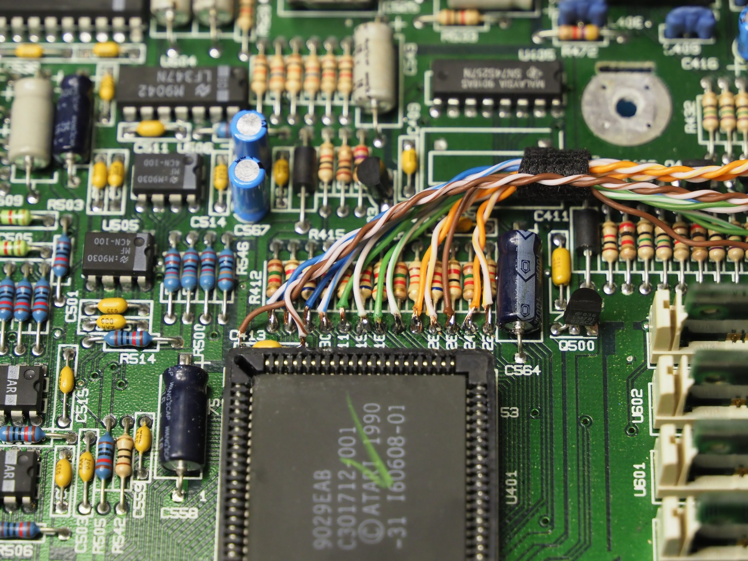
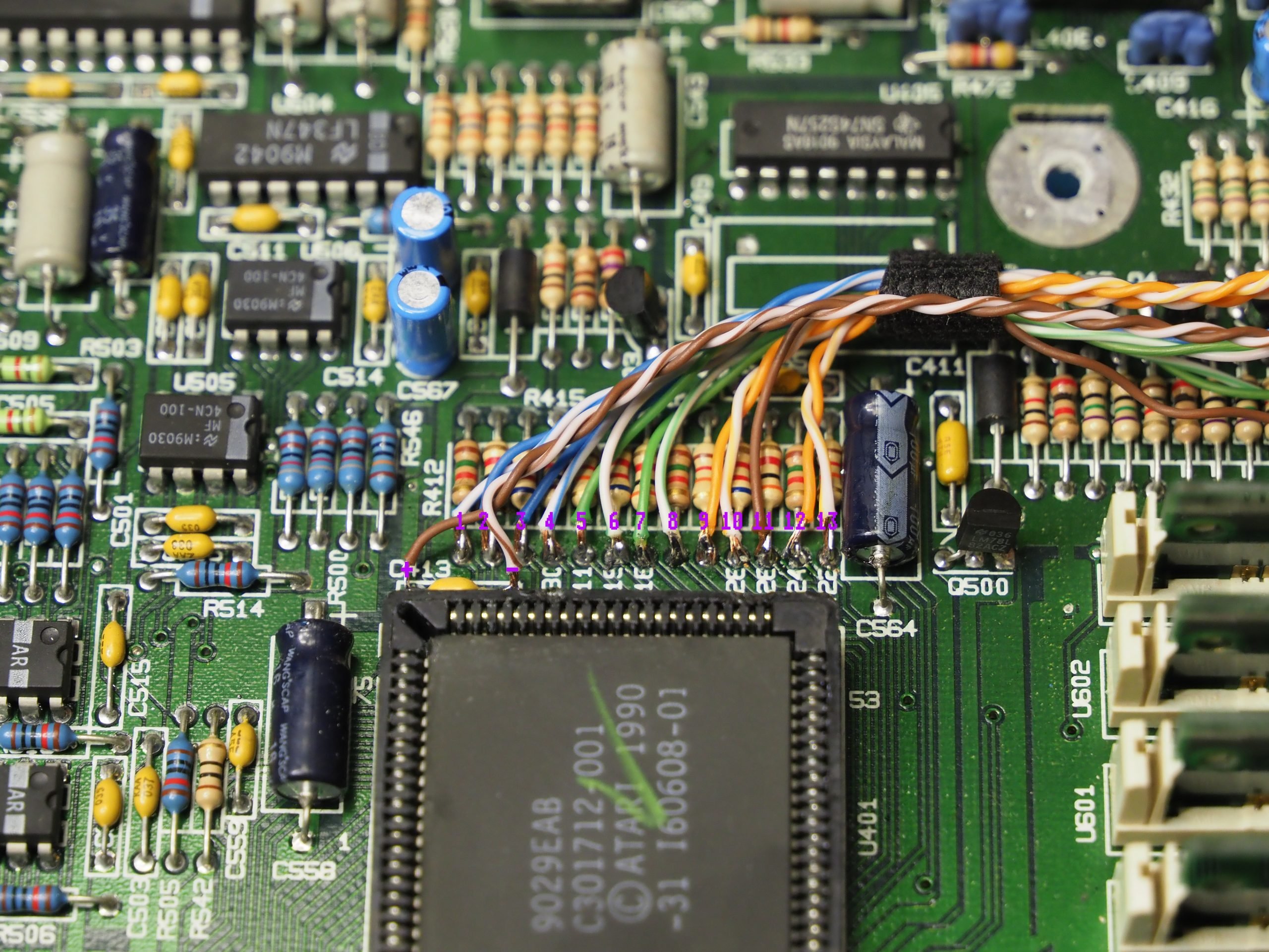
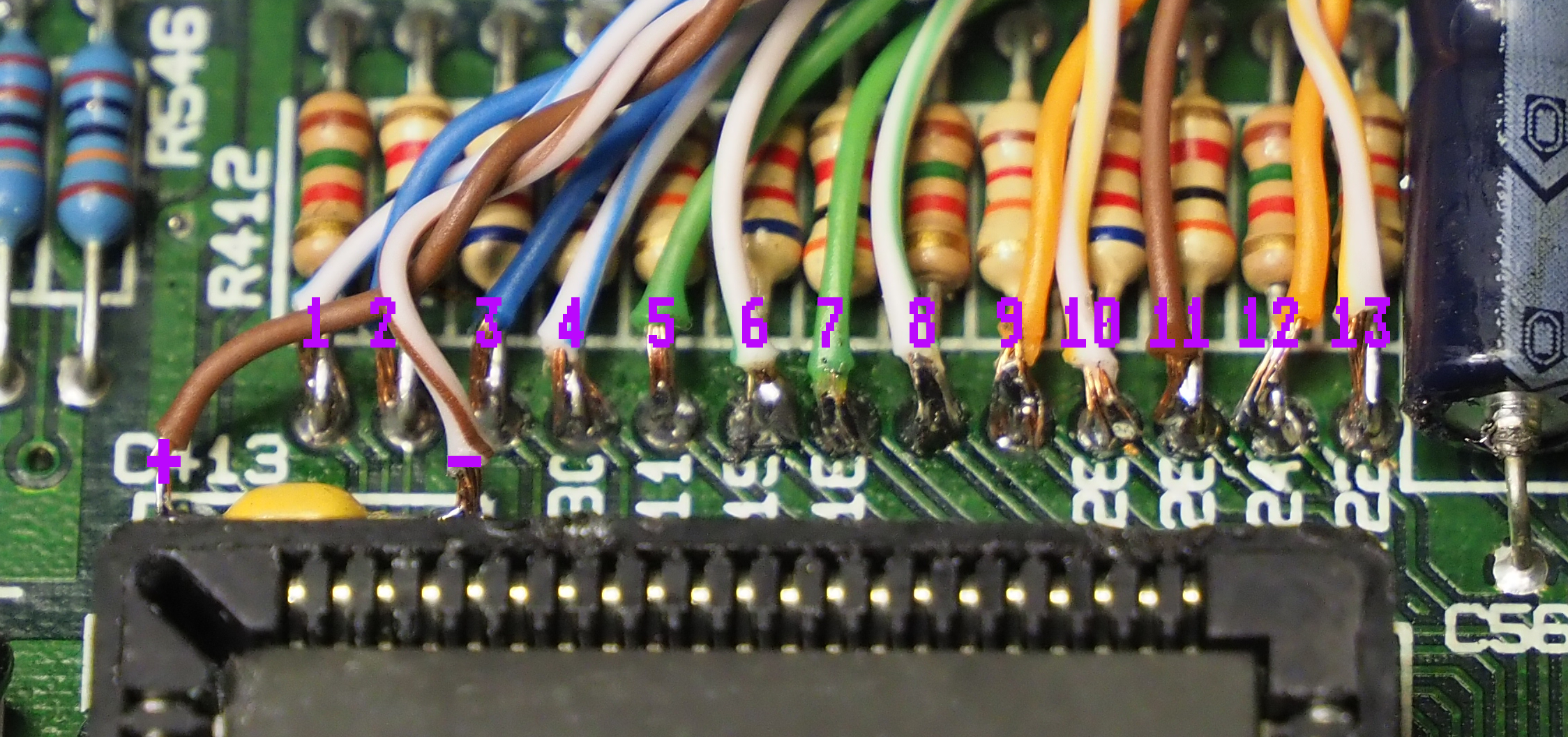
As you can see above we need to attache the signals 1 to 13 as well as +5V and GND (-). What is left is the C-SYNC signal:
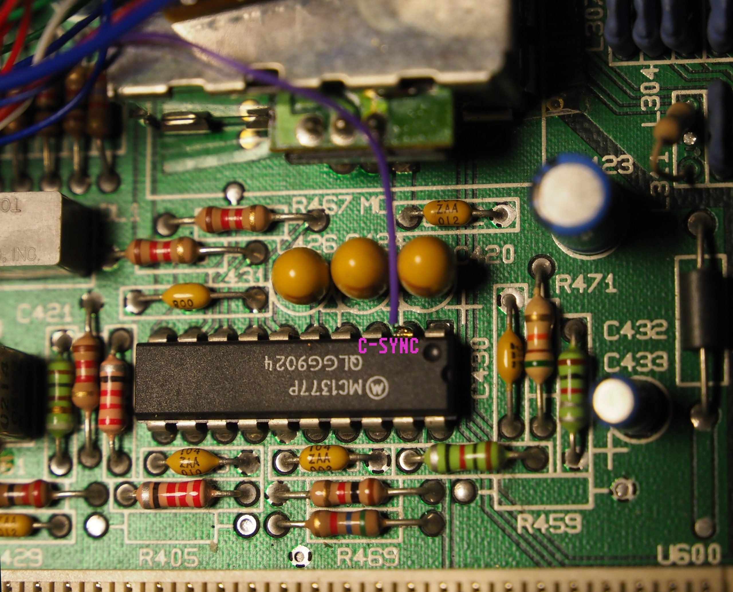
Do mind that some ATARI STE may not have the MC1377P chip as they are not modulator equipped. This is exactly what my friend Flor Kendall notice on his STE and helped me here with following my steps as well as posting this alternative C-SYNC source:
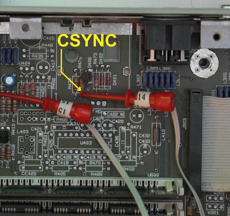
That's it!

This work is licensed under a Creative Commons Attribution-NonCommercial-NoDerivatives 4.0 International License (c) 2014-2024 Łukasz C. Jokiel, [CC BY-NC-SA 4.0 DEED](https://creativecommons.org/licenses/by-nc-sa/4.0/)