SMOG & ESP8266 Part 3: Protecting the sensor and sending data to the cloud
Last time we updated our simple SMOG sensor with display (OLED) and added BME 280 to verify the SMOG measurements – the environmental sensor – as we know that humidity over 70% can add up to the SMOG. It’s time now to protect our sensor and send the data to cloud.
Why do we need to protect the sensor? From what?
The SMOG sensor – it’s laser in particular – has a limited lifetime – it's datasheet states 8000 hours. Both the fan and the laser diode should not work continuously – because of wear and tear and also – it clogs the senor with dust. The idea is to only turn it on when it is really needed – for the time of measurement. Of course SDS011 supports sleep mode – “software off”, and this is obviously the best and natural way to protect it. I decided not to use it because it is not yet available in ESP Easy 2.0-dev-12, and also because the relay gives us the possibility of turning on an additional element – the inlet air heater, to avoid measuring errors with humidity> 70%, a idea for future extension of the project.
What new things will you need?
Hardware
- working SMOG sensor from previous entry, the SDS011
- A relay – this example features dedicated relay for the Wemos D1 mini, since it reduces the number of connections and saves space. And because I just had it lying around, but it can be any relay activated high status 3.3V and powered 5V.
- additional red and orange jumper cable
Software
- ESP Easy – already installed in previous step on the ESP8266 which is needed to control our SDS011 sensor
Let’s do it!
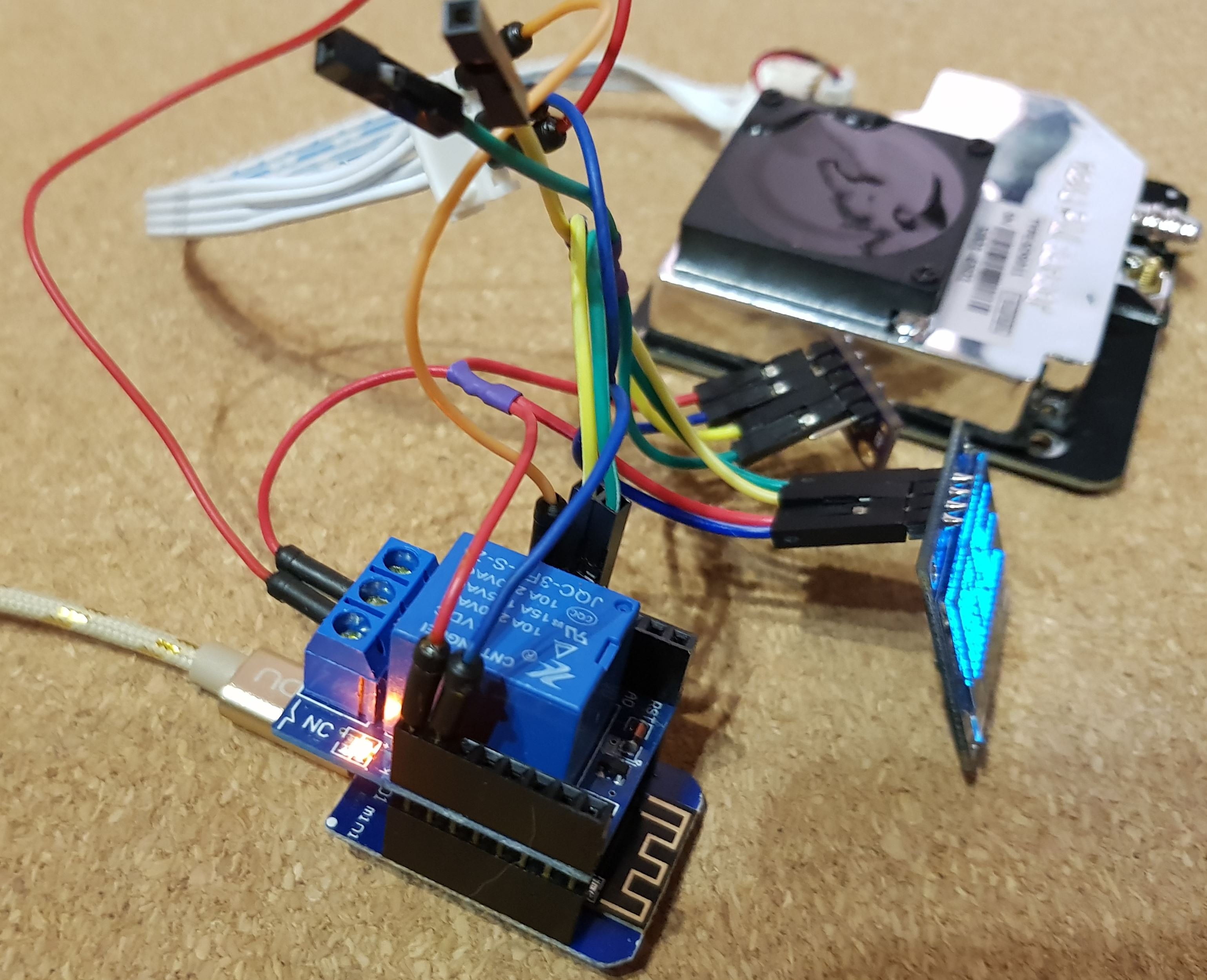
Connect anew all the wires – use the schema and pictures. We already know the drill – VCC power on red cables, blue – GND. The new part is the relay
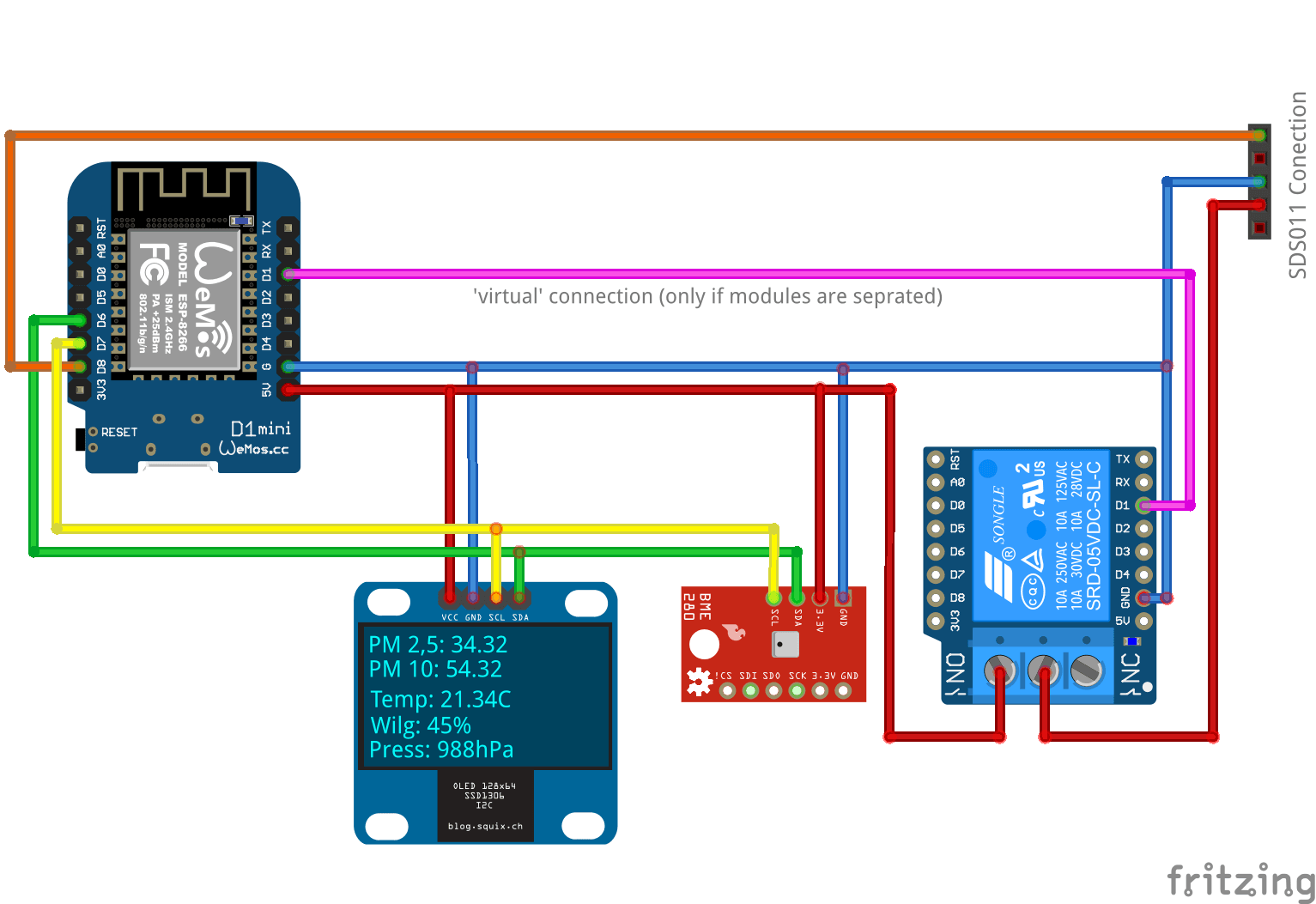
We connect in accordance with the diagram – please do mind that we change the pins, because of the Wemos D1 Relay shield. CAUTION – do not connect the power supply (+5V) until you make software changes to ESP Easy (below)
New version – our monster grows bigger!
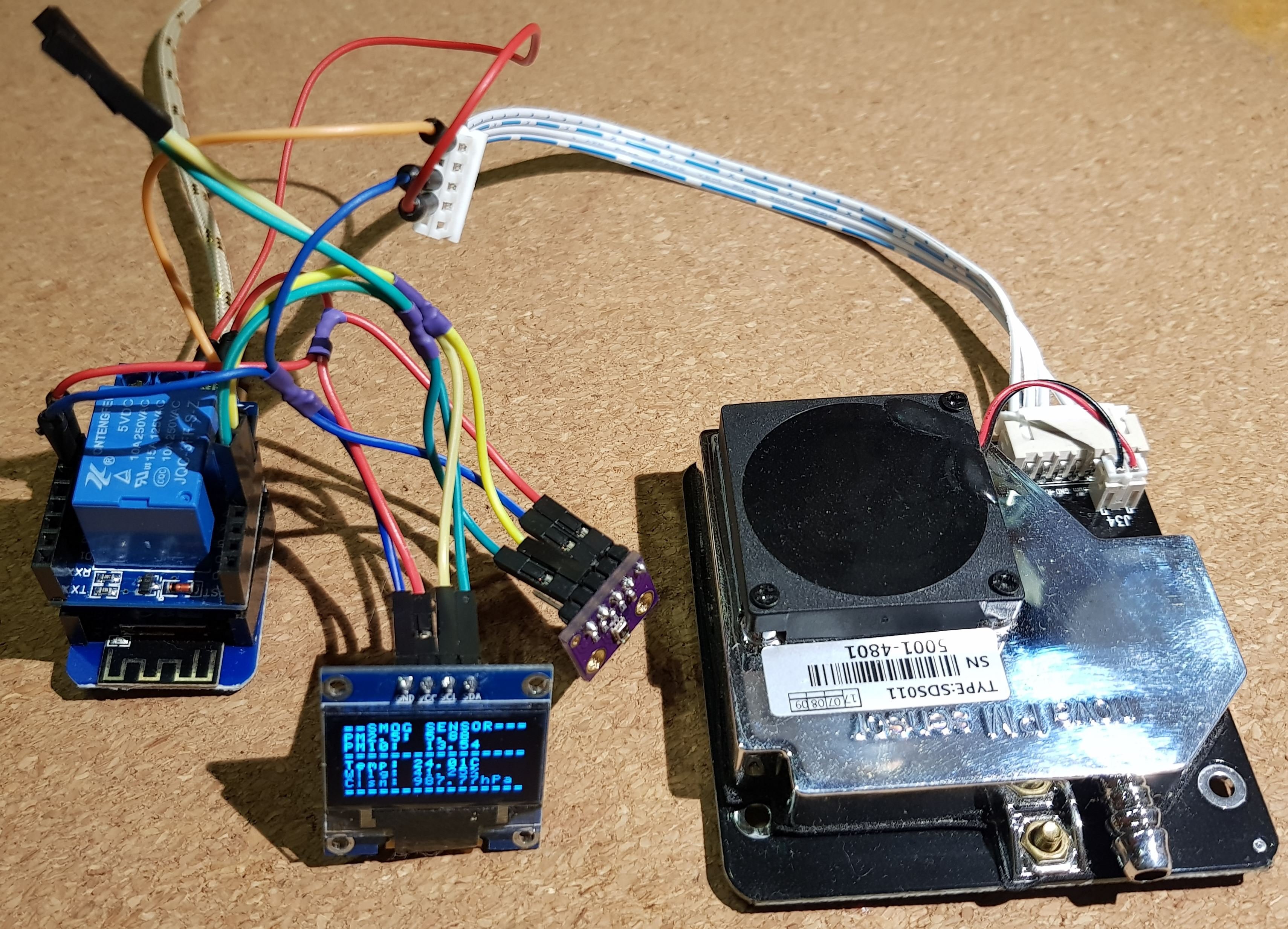
Since we have an additional element that consumes electricity – let’s see how much mA will we need to power the solution:
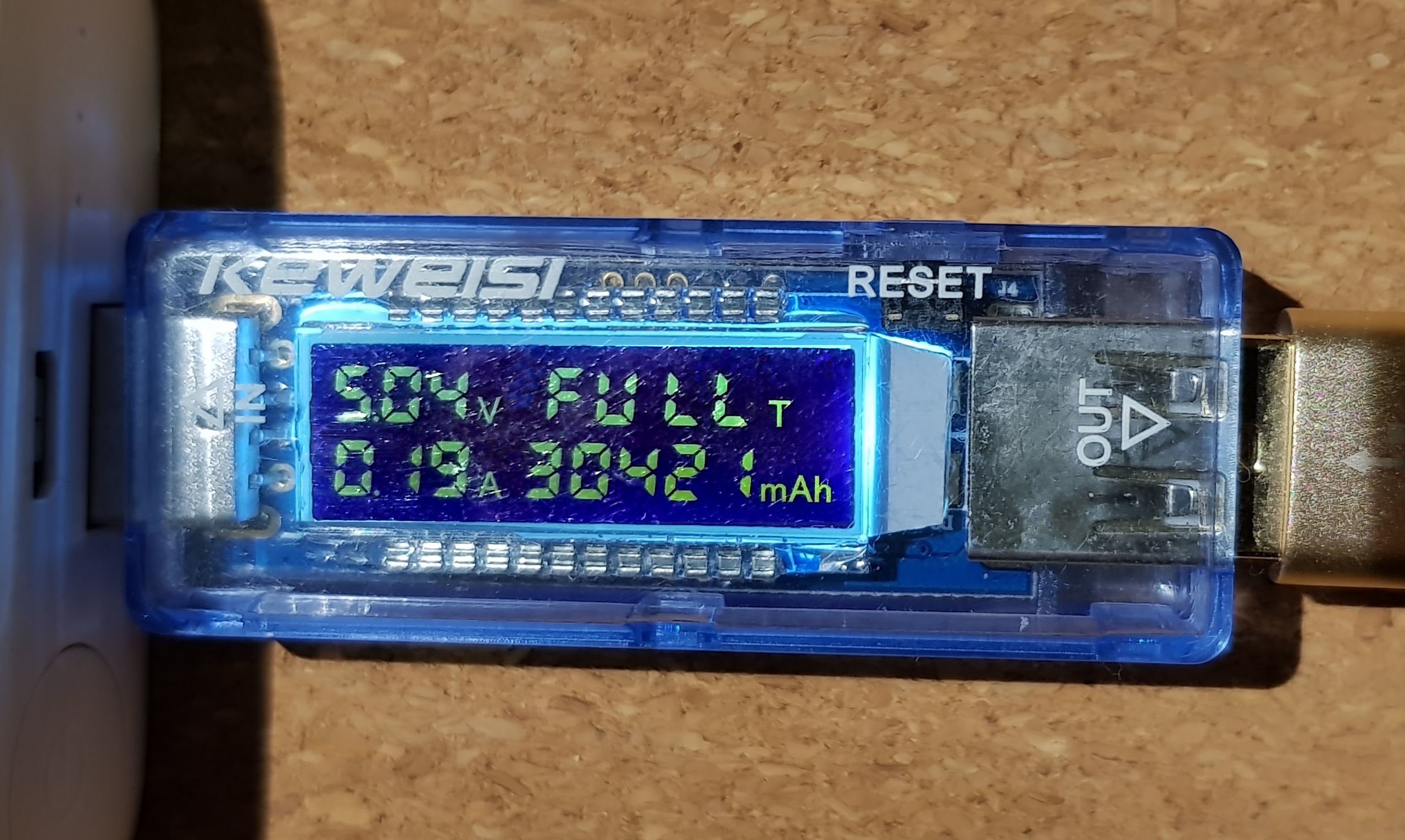
We can see maximum of 200mA when all elements are active and data is sent over WiFi network. Also – 50mA when relay and SDS011 are off and ESP does not send any data.
Now – let’s move to software – the needed changes in ESPEasy configuration: - We have to change the pins used to communicate with the I2C bus to D6 and D7, and set the low state at the boot – to make sure the relay is not powered (just in case)
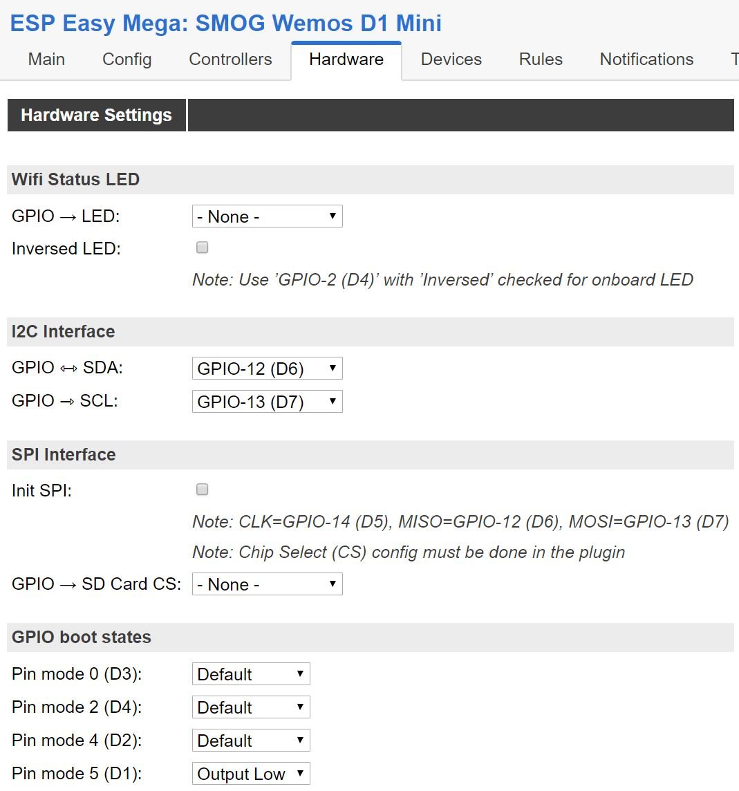
- Turn on the Rules in Tools -> Advanced

- Next – change the GPIO port of our sensor to GPIO-15 (D8) – as in the connection diagram:
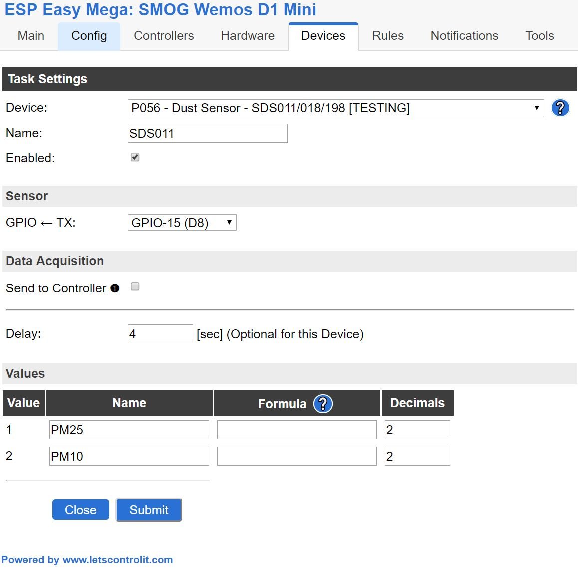
We will remove the information about PM2,5 and PM10 from the SSD1306, but don’t worry – this is just temporary we will still display this data, but in a different way
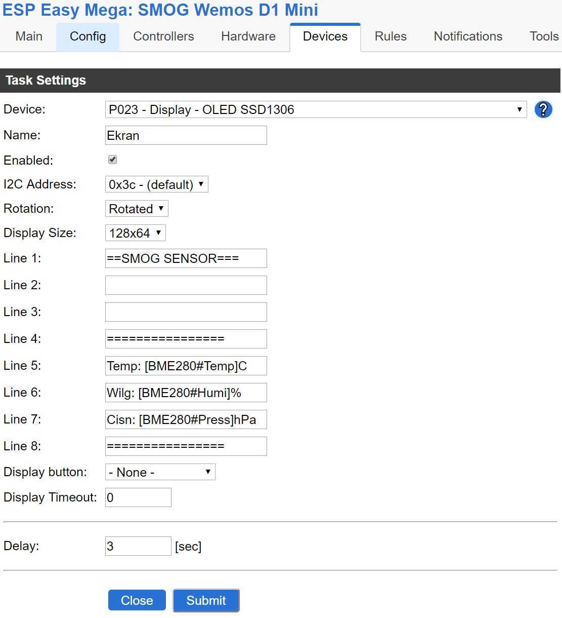
Rules
Time to use new functionality – Rules on ESP Easy. Rules are the way to perform actions, and we can do it in loops. They might also depend on different parameters. We will use them to:
switch the sensor on after 30 seconds counting from the boot of ESP8266
Have it running for 120 seconds…
After 120 seconds – record the data – send them to already known to you Domoticza and InfluxDB/Grafanie for presentation and graphs
Update the OLED screen
Wait 720 seconds (12 minutes) and repeat
How? Just paste the script into rules Rules:
On System#Boot do //To wydarzy sie po uruchomieniu ESP8266
timerSet,1,30 //Ustaw zegar do pierwszego pomiaru na 30 sekund
endon
On Rules#Timer=1 do //Gdy czas Timer 1 uplynie to:
GPIO,5,1 //Wlacz SDS011
timerSet,2,120 //Poczekaj 120 sekund az SDS011 sie rozkreci
endon
On Rules#Timer=2 do //Gdy czas Timer 2 uplynie to:
SendToHTTP 10.20.30.40,8080,/json.htm?type=command¶m=udevice&idx=11&nvalue=0&svalue=[SDS011#PM25] //Wysylam PM2,5 do Domoticza
SendToHTTP 10.20.30.40,8080,/json.htm?type=command¶m=udevice&idx=12&nvalue=0&svalue=[SDS011#PM10] //Wysylam PM10 do Domoticza
OLED,2,1,PM2.5: [SDS011#PM25] //Wyswietlaj na OLEDzie
OLED,3,1,PM10: [SDS011#PM10] //Wyswietlaj na OLEDzie
GPIO,5,0 //Wylacz SDS011
timerSet,1,720 //Ustaw nastepny pomiar za 720 sekund
endonThis is how it looks (comments in Polish from older screenshot):
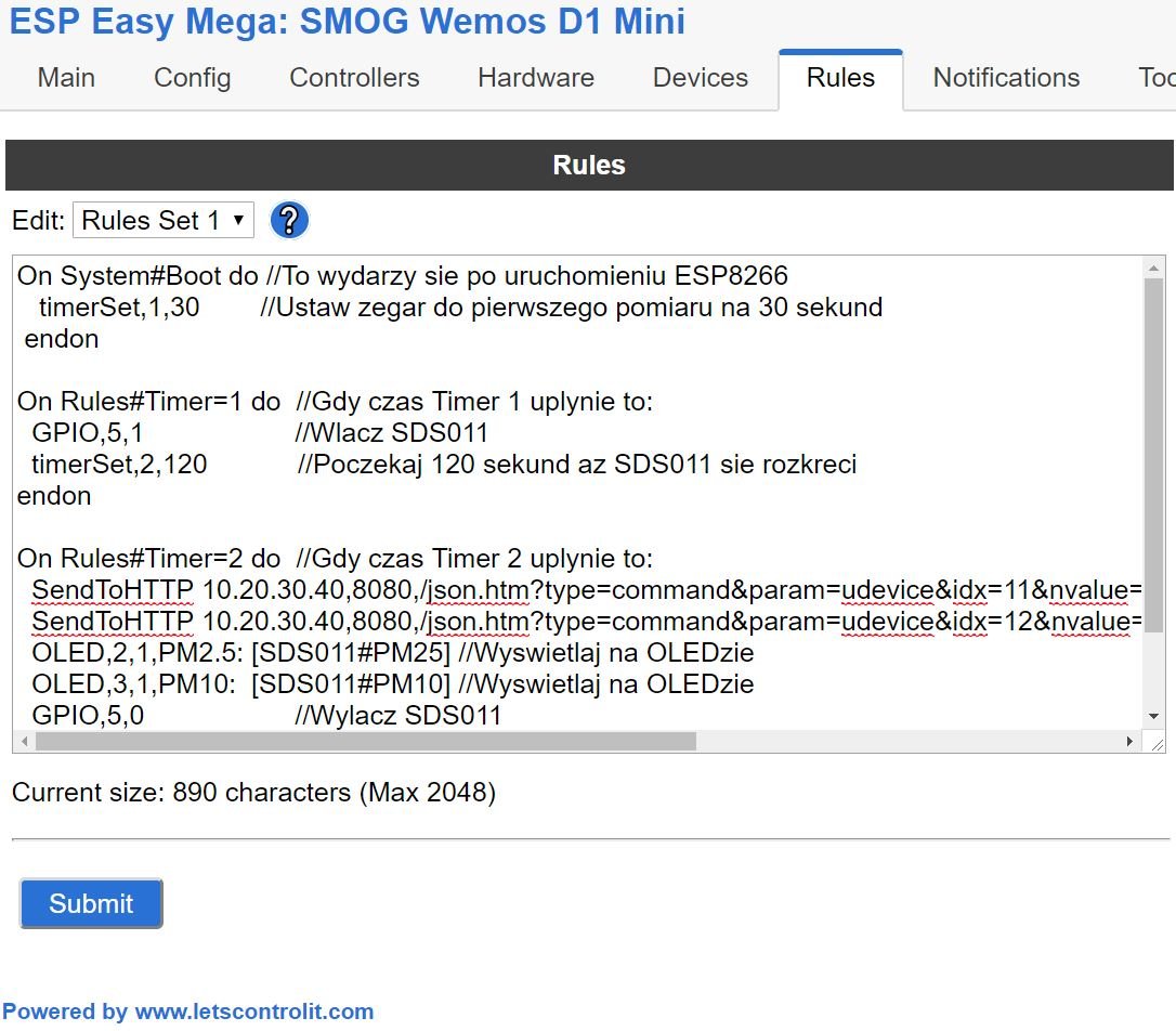
Note that the script lines will display the measured values on the OLED screen – only the ones that will be measured (otherwise when SDS011 is switched off – we would see ‘nan’ values).
Now create in Domoticz (Check out the the “dummy sensor creation” sensor entry) virtual sensors – separately for PM 2.5 and PM 10. Use the “Custom sensor” from drop-down list. The Rules scripts assumes the IDX values of 11 and 12 – change it to yours, just as the IP address and port of the domoricz.
Power on our sensor and observe the first data after around 16 minutes of running:

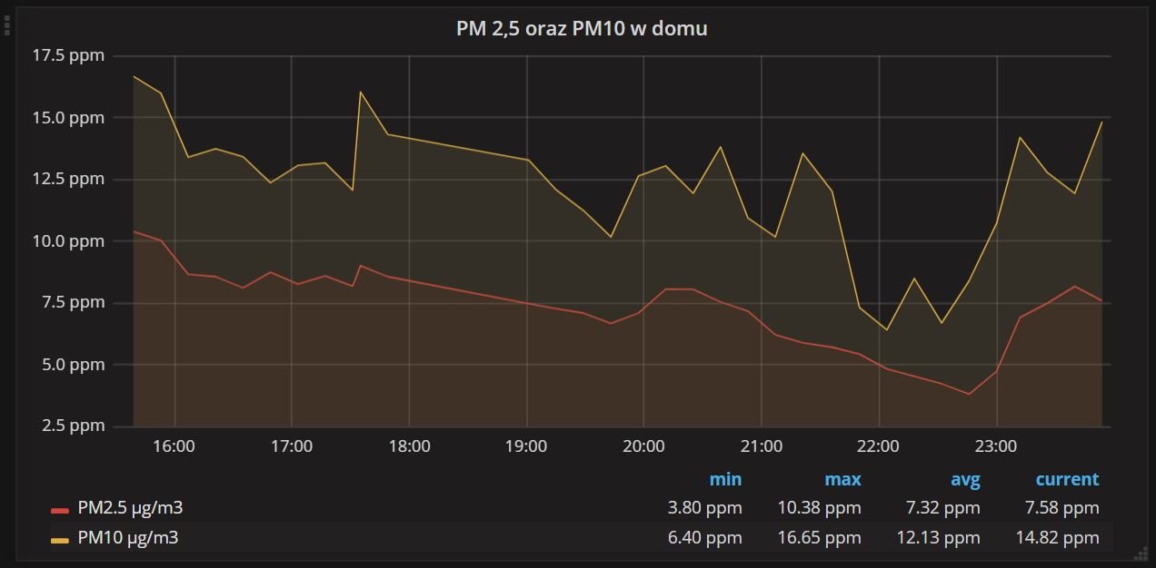
The final move is to configure data connection from Domoticz InfluxDB and Grafana. Another option is to send the BME280 data – and I suggest to do it every 5 minutes. Our sensor is ready!

This work is licensed under a Creative Commons Attribution-NonCommercial-NoDerivatives 4.0 International License (c) 2014-2024 Łukasz C. Jokiel, [CC BY-NC-SA 4.0 DEED](https://creativecommons.org/licenses/by-nc-sa/4.0/)